SPT7936 查看數據表(PDF) - Signal Processing Technologies
零件编号
产品描述 (功能)
比赛名单
SPT7936 Datasheet PDF : 8 Pages
| |||
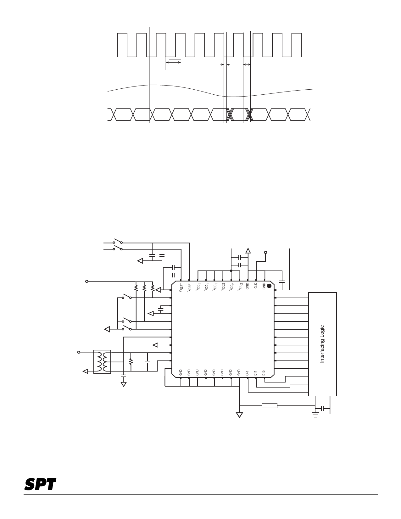
Figure 1 - Timing Diagram
Clock
S
S
S
A
MN
P
A
M N+1
P
tAP
A
M
N+2
P
tH
tD
L
L
L
E
E
E
Analog Input
Data
Data
N-1
Data
N
Data
N+1
GENERAL DESCRIPTION
The SPT7936 is a low power, 12-bit, 28 MSPS ADC. It has a
pipelined architecture and incorporates digital error correc-
tion of the 11 most significant bits. This error correction
ensures good linearity performance for input frequencies up
to Nyquist. The inputs are fully differential, making the device
insensitive to system-level noise. This device can also be
used in a single-ended mode. (See analog input section.)
With the power dissipation roughly proportional to the sam-
Figure 2 - Typical Interface Circuit
pling rate, this device is ideal for very low power applications
in the range of 1 to 28 MSPS.
TYPICAL INTERFACE CIRCUIT
The SPT7936 requires few external components to achieve
the stated operation and performance. Figure 2 shows the
typical interface requirements when using the SPT7936 in
normal circuit operation. The following sections provide a descrip-
tion of the functions and outline critical performance criteria to
consider for achieving the optimal device performance.
+1.0 V
+2.0 V
+3.3 V
4.7 µF +
+ 4.7 µF
.01µF
1 kΩ
ExtRef
.01µF
1 kΩ
1 kΩ
N/C
ExtRef
.01 µF
BGAP
+3.3 V
4.7 µF
+
Clock Input
(3.3 V Logic)
+3.3 V
.01
µF
.01 µF
VDD2
D0
D1
(LSB)
Bias0
Bias1
GND
D2
Bias0
D3
Bias1
SPT7936
D4
CM
D5
GND
D6
VIN
VIN+
D7
50 Ω 68 pF
VIN-
D8
GND
D9
NOTES:
Mini-Circuit
T1-6T
.01µF
(MSB)
1) Place the ferrite bead (*) as close to the device as possible.
2) Place 0.01 microfarad capacitors as close to the device as possible.
3) All capacitors are surface-mount unless otherwise specified.
FB
4) All input pins (references, analog input, clock input) must be
protected. (See absolute maximum rating.)
(*)
5) Set Bias1 and Bias0 for maximum sample rate.
Bias1Bias0
0 0 Sleep mode
0 1 Max. 5 MHz sampling
1 0 Max. 20 MHz sampling
1 1 Max. 28 MHz sampling
6) Use internal or external reference. Do not connect external voltage reference when using internal references.
7) All VDD1 and VDD2 must be connected together. Do not leave any pin unconnected.
8) All GND must be connected together. Do not leave any pin unconnected.
+3.3 V
SPT
5
SPT7936
8/1/00
Share Link: 