MK50H27 查看數據表(PDF) - STMicroelectronics
零件编号
产品描述 (功能)
比赛名单
MK50H27 Datasheet PDF : 56 Pages
| |||
MK50H27
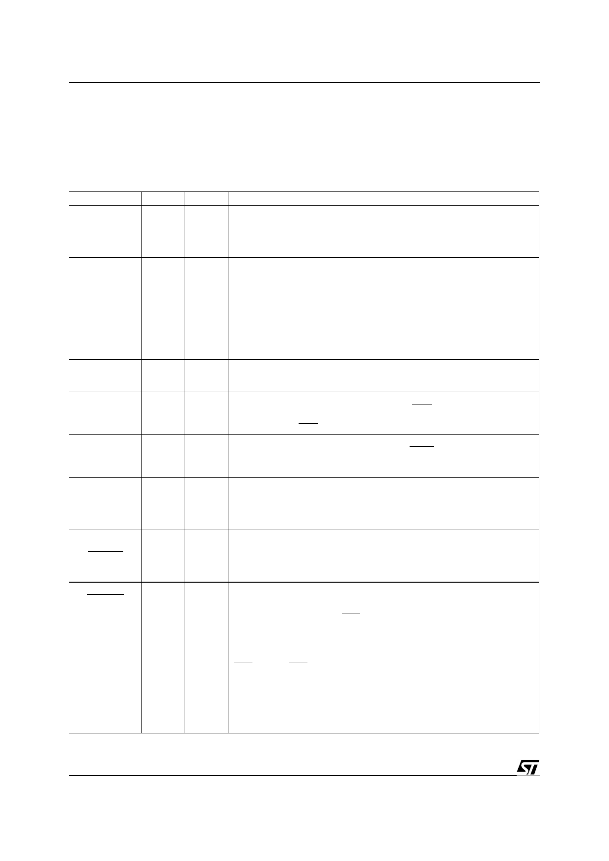
TAble 1 - PIN DESCRIPTION
LEGEND:
I
Input only
O
IO
Input / Output
3S
OD Open Drain (no internal pull-up)
Output only
3-State
Note: Pin out for 52 pin PLCC is shown in brackets.
SIGNAL NAME
DAL<15:00>
PIN(S)
2-9
40-47
[2-10
44-51]
READ
10
[11]
INTR
11
[12]
DALI
12
[13]
DALO
13
[14]
DAS
14
[15]
BMO
15
BYTE
[16]
BUSREL
BM1
16
BUSAKO
[18]
TYPE
IO/3S
IO/3S
O/OD
O/3S
O/3S
IO/3S
IO/3S
O/3S
DESCRIPTION
The time multiplexed Data/Address bus. During the address portion of a
memory transfer, DAL<15:00> contains the lower 16 bits of the memory
address.
During the data portion of a memory transfer, DAL<15:00> contains the read
or write data, depending on the type of transfer.
READ indicates the type of operation that the bus controller is performing
during a bus transaction. READ is driven by the MK50H27 only while it is the
BUS MASTER. READ is valid during the entire bus transaction and is
tristated at all other times.
MK50H27 as a Bus Slave :
READ = HIGH - Data is placed on the DAL lines by the chip.
READ = LOW - Data is taken off the DAL lines by the chip.
MK50H27 as a Bus Master :
READ = HIGH - Data is taken off the DAL lines by the chip.
READ = LOW - Data is placed on the DAL lines by the chip.
INTERRUPT is an attention interrupt line that indicates that one or more of
the following CSR0 status flags is set: MISS, MERR, RINT, TINT or PINT.
INTERRUPT is enabled by CSR0<09>, INEA=1.
DAL IN is an external bus transceiver control line. DALI is driven by the
MK50H27 only while it is the BUS MASTER. DALI is asserted by the
MK50H27 when it reads from the DAL lines during the data portion of a
READ transfer. DALI is not asserted during a WRITE transfer.
DAL OUT is an external bus transceiver control line. DALO is driven by the
MK50H27 only while it is the BUS MASTER. DALO is asserted by the
MK50H27 when it drives the DAL lines during the address portion of a READ
transfer or for the duration of a WRITE transfer.
DATA STROBE defines the data portion of a bus transaction. By definition,
data is stable and valid at the low to high transition of DAS. This signal is
driven by the MK50H27 while it is the BUS MASTER. During the BUS
SLAVE operation, this pin is used as an input. At all other times the signal is
tristated.
I/O pins 15 and 16 are programmable through CSR4. If bit 06 of CSR4 is set
to a one, pin 15 becomes input BUSREL and is used by the host to signal
the MK50H27 to terminate a DMA burst after the current bus transfer has
completed. If bit 06 is clear then pin 15 is an output and behaves as
described below for pin 16.
Pins 15 and 16 are programmable through bit 00 of CSR4 (BCON).
If CSR4<00> BCON = 0,
I/O PIN 15 = BMO (O/3S)
I/O PIN 16 = BM1 (O/3S)
BYTE MASK<1:0> Indicates the byte(s) on the DAL to be read or written
during this bus transaction. MK50H27 drives these lines only as a Bus
Master. MK50H27 ignores the BM lines when it is a Bus Slave.
Byte selection is done as outlined in the following table.
BM1
BM0
TYPE OF TRANSFER
LOW
LOW
ENTIRE WORD
LOW
HIGH
UPPER BYTE
(DAL<15:08>)
HIGH
LOW
LOWER BYTE
(DAL<07:00>)
HIGH
HIGH
NONE
4/56
Share Link: 