SP6642EU 查看數據表(PDF) - Signal Processing Technologies
零件编号
产品描述 (功能)
比赛名单
SP6642EU Datasheet PDF : 16 Pages
| |||
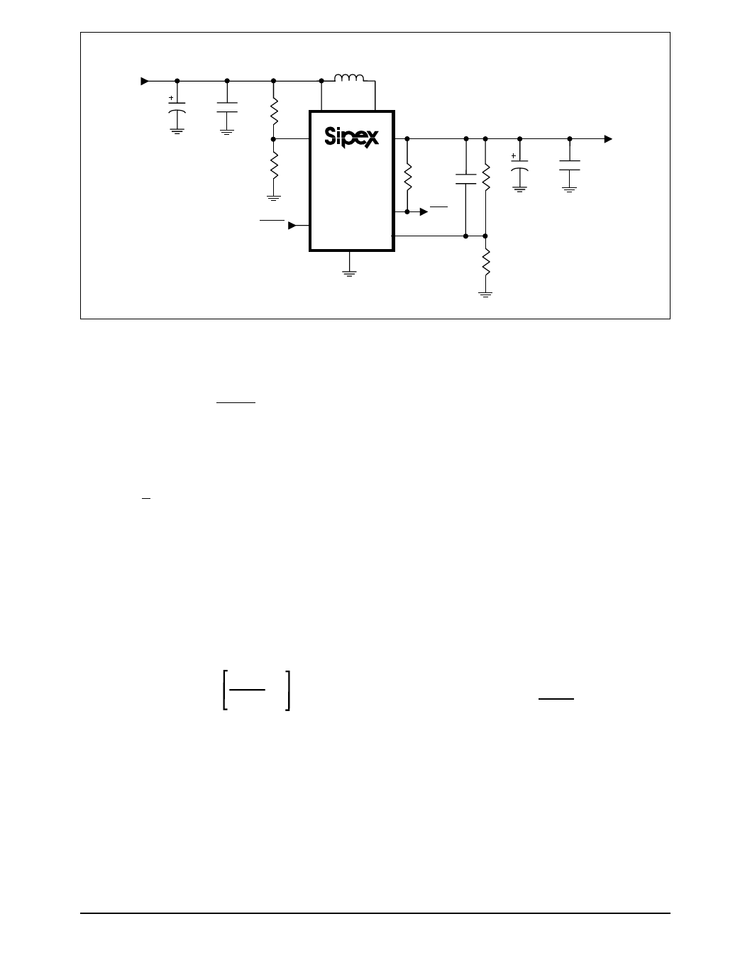
0.88V to
1.65V Input
22µF
100µH
350mA
0.1µF
VBATT
LX
PFI
SP6642
VOUT
100pF*
SHDN
PFO
FB
GND
22µF
R1
VOUT=
2V to 5.2V
0.1µF
*optional compensation
R2
Figure 25. Adjustable Output Voltage Circuitry
synchronous-rectifier body diode from the input
to the output. To disable the shutdown feature,
designers can connect SHDN to V .
BATT
Adjustable Output Voltage
Driving FB to ground (logic LOW) will drive
the output voltage to the fixed-voltage operation
of +3.3V + 4%. Connecting FB to a voltage
divider between VOUT and ground will select an
adjustable output voltage between +2V and
+5.5V. Refer to Figure 25. FB regulates to
+1.23V.
Since the FB leakage current is 10nA maximum,
designers should select the feedback resistor R2
in the 100kΩ to 1MΩ range. R1 can be
determined with the following equation:
R1 = R2 x
VOUT
VREF
-1
where R3 and R4 are the feedback resistors in
Figure 25, VOUT is the output voltage, and VREF
is 1.23V.
Battery Reversal Protection
The SP6642/6643 devices will tolerate single-
cell battery reversal up to the package power-
dissipation limits noted in the ABSOLUTE
MAXIMUM RATINGS section. An internal
diode in series with an internal 5Ω resistor limits
any reverse current to less than 220mA
preventing damage to the devices. Prolonged
operation above 220mA reverse-battery current
can degrade performance of the devices.
The Inductor
It is recommended that designers implement a
100µH inductor for typical application of the
SP6642/6643 devices. Lower inductor values
down to 68µH will increase the maximum
output current. Higher inductor values up to
220µH will reduce peak inductor current and
any consequent ripple and noise. The saturation-
current rating of the inductor selected must
exceed the peak current limit synthesized by the
SP6642/6643 devices' timing algorithms. This
can be calculated with the following equation:
IPEAK =
KMAX
LMIN
where
I
PEAK
is
the
peak
current,
K
MAX
is
35V-µs,
and LMIN is the minimum inductance selected.
The maximum recommended IPEAK is 350mA.
To optimize efficiency, select an inductor with
a series resistance less than 1Ω.
Table 1 lists surface mount inductor information
for the user, including series resistance and
saturation current rating.
Rev. 10-6-00
SP6642/6643 High Efficiency Step-Up DC-DC Converter
13
© Copyright 2000 Sipex Corporation
Share Link: 