M56786FP 查看數據表(PDF) - MITSUBISHI ELECTRIC
零件编号
产品描述 (功能)
比赛名单
M56786FP Datasheet PDF : 10 Pages
| |||
MITSUBISHI <CONTROL / DRIVER IC>
M56786FP
SPINDLE MOTOR AND 1CH ACTUATOR DRIVER
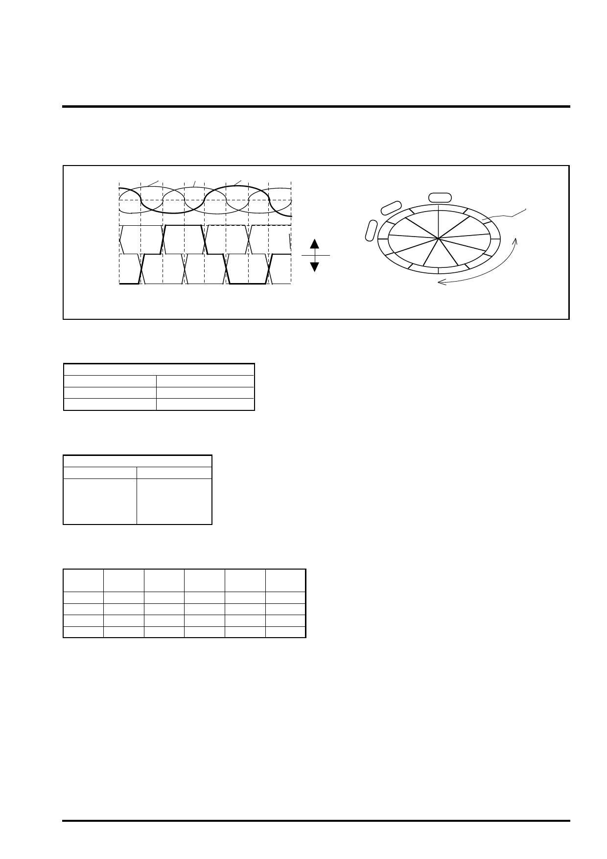
HALL AMPLIFIER INPUT AND COMMUTATION
The relationship between the hall amplifier inputs voltage and the
motor current outputs is shown in Figure 4.
Hw+
Hv+
Hu+
Hall
inputs
V
U
W
V
Output
current
U
W
V
U
Hall elements
U
V
SOURSE
W
U
V
W
U
W
V
U
W
V
SINK
W
FORWARD
EC<ECR
Outer loator
REVERSE
EC>ECR
Figure 4.
BRAKING MODE SELECT FUNCTION
Braking mode select [BRS] pin
HIGH
SHORT BRAKE
OPEN
FREE RUN
LOW
REVERSE BRAKE
Figure 5.
FG FUNCTION
FG pulse select (FGSpin)
LOW or OPEN
HIGH
NX1 pulse
NX3 pulse
Figure 6.
SLEEP MODE FUNCTION and MUTE FUNCTION
S/S
MUTE
Spindle
Hall bias
HS /S H M UOTN E
H
L,OPEN ON
L,OPEN
H
OFF
L,OPEN L,OPEN OFF
Actuator
CIRCUIT
ON
OFF
ON
OFF
BIAS
CIRCUIT
ON
ON
ON
OFF
TSD
CIRCUIT
ON
ON
ON
OFF
Figure 7.
It is possible to select three kinds of mode [the reverse braking, the
short braking and the free run] in reverse torque by logic control
using the BRS terminal.
Figure 5 shows the function table of the braking mode select.
It is the reverse braking when BRS is LOW, the short braking when
BRS is HIGH and the free run when BRS is OPEN.
It is possible for user to switch the output pulse numeric by external
logic control using FG pulse select terminal [FGS].
Figure 6 shows the FG pulse select function.
The FG pin outputs the square pulse signal synchronizing with the
hall inputs [Hv+ and Hv-] timming when FGS=LOW or OPEN.
When FGS=HIGH, it outputs the square pulse signal of 3 times.
The FG pin is pulled-up to VCC1 by an internal resistor [typ.
10Kohm].
This IC has the S/S terminal (S/S) for ON/OFF of the Spindle motor
drive and the MUTE terminal (MUTE) for ON/OFF of the actuator
drive.
It is possible to control ON / OFF of each circuit (SPM, Actuator) by
external logic inputs.
The figure 7 shows its function.
In case of both S/S and MUTE is LOW or OPEN, the bias of all
circuit becomes OFF[Current is zero].
Therefore, this mode is available in order to reduce the power
dissipation when the waiting mode.
Share Link: 