PBL38582 查看數據表(PDF) - Ericsson
零件编号
产品描述 (功能)
比赛名单
PBL38582 Datasheet PDF : 9 Pages
| |||
PBL 385 82
Functional description
Design procedure; ref. to fig.4.
The design is made easier through that all
settable parameters are returned to gro-
und (-line), this feature differs it from bridge
type solutions.To set the parameters in the
following order will result in that the
interaction between the same is minimized.
1. Set the circuit impedance to the line,
either 600Ω or complex. (R3 and C1). C1
should be big enough to give low
impedance compared with R3 in the
telephone speech frequency band.Too
large C1 will make the start-up slow. See
fig. 10.
2. Set the DC-characteristic that is
required in the PTT specification or in case
of a system telephone,in the PBX
specification (R6).There are also internal
circuit dependent requirements like supply
voltages etc.
3. Set the attac point where the line
length regulation ( if used ) is supposed to
cut in. Note that in some countries the line
length regulation is not allowed. In most
cases the end result is better and more
readily achieved by using the line length
regulation (line loss compensation) than
without.
4. Set the transmitter gain and
frequency response.
5. Set the receiver gain and frequency
response. See text how to limit the max.
swing.
6. Adjust the side tone balancing
network if used.The network in most cases
is just a coarse resistive divider to take
care of the first order of balancing. The fine
balancing is done by the DSP in the sys-
tem.
7. Set the RFI suppression
components in case necessary.
8. Circuit protection. Apart from any
other protection devices used in the de-
sign a good practice is to connect a 15V
1W zener diode across the circuit , from
pin 1 to -Line.
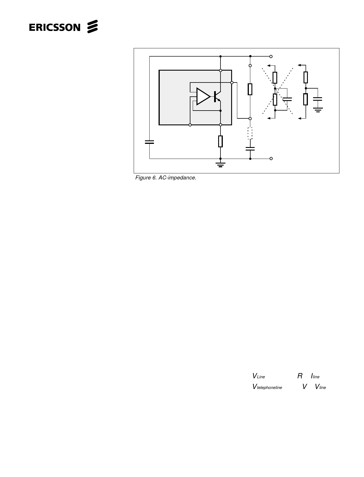
Impedance to the line
The AC- impedance to the line is
set by R3, C1 and C2. Fig.6. The circuits
relatively high parallel impedance will not
influence the line impedance to any
noticeable extent.At low frequencies the
influence of C1 can not be neglected.
Series resistance of C1 that
PBL 38 582
a)
1
4
+Line
b)
R3
820Ω
c)
220Ω
C
3
C2
2
R6
Rs
≈1Ω
+
C1
Example:
How to connect a
complex network.
220Ω+820Ω//C
-Line
Figure 6. AC-impedance.
is dependent on the temperature and the
quality of the component will cause some
of the line signal to enter pin 4. This
generates a closed loop in the transmitter
amplifier that in it´s turn will create an
active impedance thus lowering the
impedance to the line. The impedance at
high frequencies is set by C2 that also
acts as a RFI suppressor.
In many specifications the
impedance towards the line is specified as
a complex network. See fig. 6. In case a).
the error signal entering pin 4 is set by the
ratio ≈Rs/R3 (909Ω), where in case b). the
ratio at high frequencies will be Rs/220Ω
because the 820Ω resistor is bypassed by
a capacitor. To help up this situation the
complex network capacitor is connected
directly to ground, case c). making the ratio
Rs/220Ω+820Ω and thus lessening the
error signal. Conclusion: Connect like in
case c) when complex impedance is
specified.
DC - characteristic
The DC - characteristic that a
telephone set has to fulfill is mainly given
by the network administrator. Following
parameters are useful to know when the
DC behaviour of the telephone is to be set:
• The voltage of the feeding system
• The line feeding resistance 2 x.......
ohms.
• The maximum current from the line at
zero line length.
• The min. current at which the telephone
has to work (basic function).
• The lowest and highest voltage
permissible across the telephone set.
• The highest voltage that the
telephone may have at different line
currents. Normally set by the
network owners specification.The
lowest voltage for the telephone is
normally set by the voltages that are
needed for the different parts of the
telephone to function. For ex. for
transmitter output amplifier, recei-
ver output amplifier, dialler, speech
switching. R6 will set the slope of the
DC-char. and the rest of the level is
set by some constants in the circuit
as shown in the equation below. The
slope of the DC-char. will also
influence the line length regulation
(when used ) and thus the gain of
both transmitter and receiver. See
the table under gain regulation. R6
also acts as power protection for the
circuit, this must be kept in mind
when low values of R6 are conside-
red. See fig. 7.
VLine ≈ 2 + 1. 5 ⋅R 6 ⋅Iline
Vtelephoneline ≈ 1. 5V + Vline
5
Share Link: 