G768D 查看數據表(PDF) - Global Mixed-mode Technology Inc
零件编号
产品描述 (功能)
比赛名单
G768D
Global Mixed-mode Technology Inc

G768D Datasheet PDF : 16 Pages
| |||
Global Mixed-mode Technology Inc.
G768D
Twisted Pair and Shielded Cables
For remote-sensor distances longer than 8 in., or in
particularly noisy environments, a twisted pair is rec-
ommended. Its practical length is 6 feet to 12feet (typi-
cal) before noise becomes a problem, as tested in a
noisy electronics laboratory. For longer distances, the
best solution is a shielded twisted pair like that used
for audio microphones. Connect the twisted pair to
DXP and DXN and the shield to GND, and leave the
shield's remote end unterminated.
Excess capacitance at DX_limits practical remote
sensor distances (see Typical Operating Characteris-
tics), For very long cable runs, the cable's parasitic
capacitance often provides noise filtering, so the
2200pF capacitor can often be removed or reduced in
value. Cable resistance also affects remote-sensor
accuracy; 1Ω series resistance introduces about + 1°C
error.
Low-Power Standby Mode
Standby mode disables the ADC and reduces the
supply-current drain to less than 10µA. Enter standby
mode via the RUN/STOP bit in the configuration byte
register. In standby mode, all data is retained in mem-
ory, and the SMB interface is alive and listening for
reads and writes. This is valid for temperature sensor
only.
Standby mode is not a shutdown mode. With activity
on the SMBus, extra supply current is drawn (see
Typical Operating Characteristics). In software
standby mode, the G768D can be forced to perform
temperature measurement via the one-shot command,
despite the RUN/STOP bit being high.
Supply-current drain during the 125ms conversion
period is always about 500µA. Slowing down the con-
version rate reduces the average supply current (see
Typical Operating Characteristics). In between con-
versions, the instantaneous supply current is about
200µA due to the current consumed by the system
resetting circuit.
Fan Controller
Since the fan speed is measured by counting the num-
ber of 32.768KHz cycles between the rising edges of
two fan speed pulses. In this way, we are actually
measuring the period of the fan speed. To avoid the
cost of doing division to obtain the speed, this count
number, N, is used in the PWM control algorithm, thus,
the desired fan speed should be programmed by writ-
ing the corresponding count number. The count num-
ber is given by:
N: Count Number
P: FG pulses number per revolution
P=1 ⇒ N = 983040 / rpm
P=2 ⇒ N = 491520 / rpm
P=4 ⇒ N = 245762 / rpm
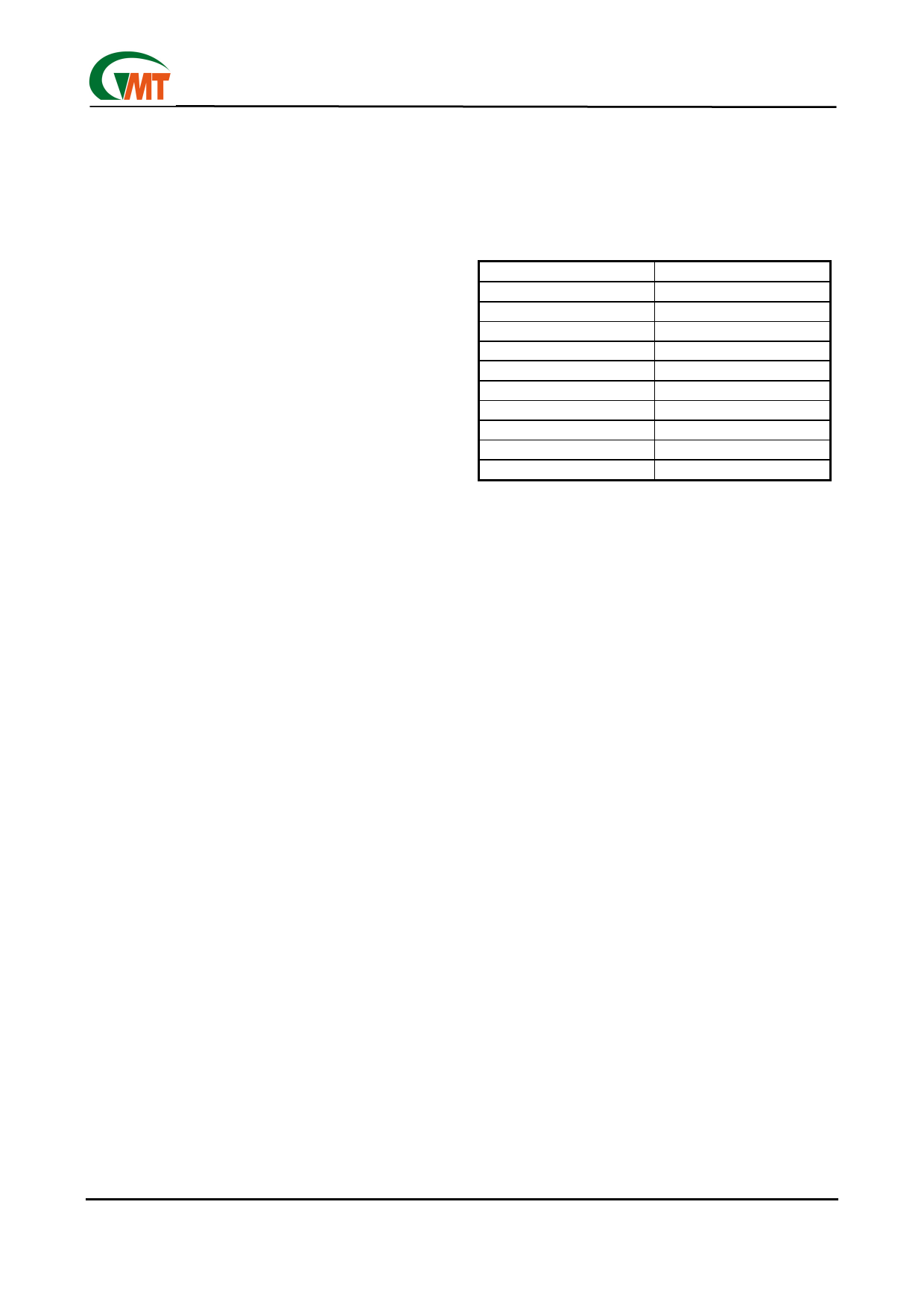
Some selected count number for P=2 are listed below.
Table 2.
Rpm
N
3000
164
4000
123
5000
98
6000
82
7000
70
8000
61
9000
55
10000
49
20000
25
30000
16
To stop the fan, program the fan speed register to 255. This
also makes the fan controller enter power saving mode.
Controlling Fan at Lower Speed
For stably controlling fans at lower rotation speed,
three schemes are recommended as below:
1.Use larger decoupling capacitors between FANVCC
and GND.
2.Shunt a capacitor of 1µF-2µF on FG pin to GND.
3.Use fans with open-collector FG outputs.
When controlling fans under lower rotation speed, the
output voltage of FANVCC would be too low for fan to
generate recognizable FG signals.
Using decouple capacitors on FANVCC and FG is to
increase the SNR on FG pins. While using fans with
open-collector FG outputs can thoroughly solve the
problem, because the logic high level of FG would be
fixed to 5V.
Reset Immunity Negative-Going VCC Transients
In addition to issuing a reset to the microprocessor (µP)
during power-up, power-down, and brownout condi-
tions, the G768D is relatively immune to short duration
negative-going VCC transients (glitches).
Typically, for the G768D, a VCC transient that goes
100mV below the reset threshold and lasts 20µs or
less will not cause a reset pulse. A 0.1µF bypass ca-
pacitor mounted as close as possible to the VCC pin
provides additional transient immunity.
Ver: 1.2
Apr 03, 2002
TEL: 886-3-5788833
http://www.gmt.com.tw
8
Share Link: