PBL3852 查看數據表(PDF) - Ericsson
零件编号
产品描述 (功能)
比赛名单
PBL3852 Datasheet PDF : 24 Pages
| |||
PBL 3852
V
16
V telephone line
14
V line
V pin 4
12
10
8
V pin 2
6
4
V pin 8
2
V pin 9
IL
20
40
60
80
100
120
mA
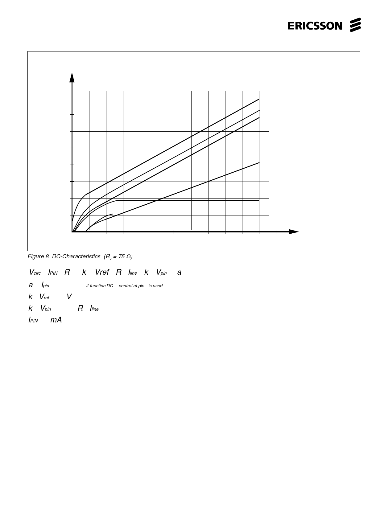
Figure 8. DC-Characteristics. (R7 = 75 Ω)
Vcirc. = IPIN4 ⋅R19 + k1⋅ Vref + R7 ⋅Iline + k 2 ⋅ Vpin2 + a
( ) a = Ipin5 ⋅ 5. 5 ⋅103 if function DC − control at pin5 is used
k1⋅ Vref = 1.1V
k 2 ⋅ Vpin2 = 0. 5 ⋅R7 ⋅Iline
IPIN4 ≈ 1mA
The R7 will set the slope of the DC-char.
and the rest of the level is set by some
constants in the circuits as shown in the
equation. The slope of the DC-char. will
also influence the line length regulation
(when used) and thus the gain of both
transmitter and receiver. R7 acts also as
current protection for the circuit, must be
considered when low values are to be
used. The level of DC-characteristic can
be adjusted up at input pin 5 (some
100mV´s). The R21 adjusts a fix amount
where R20 couples the adjusted value to
line current. See fig. 32.
Microphone amplifier
The microphone amplifier in the PBL
3852 is divided into two stages. The first
stage is a true differential amplifier
providing high CMRR (-55 to -65 dB
typical) with voltage gain of 19 dB. This via a capacitor to the - input at pin 13.
stage is followed by a gain regulated
The DC supply resistors for the
amplifier with a regulation range from 6.5 microphone should be round 200Ω (in
dB to 14.5 dB, see fig. 15. The input of order not to overdrive the microphone
the microphone amplifier can be used for amplifier) and the feedback resistor (17k)
electret, magnetic or dynamic transducers is of that magnitude that it either
see fig. 9. The PBL 3852 has basically a influences the CMRR balance at the
higher gain regulation range (8 dB) than input or destroys the send mute by
the more or less standard 6 dB´s for gain bypassing signal round the microphone
regulation with line length, this in order to amplifier in mute state. For a dynamic
be able to be used in applications where microphone some more components are
”softclipping” is required. In case lower necessary, see fig. 10c. In order not to
regulation range is necessary, it is
influence the send mute the feedback
possible with some additional
signal is taken from transmitter output at
components.
pin 2 and because this signal is in
See reference figs. 4, 10c, 10f, 32 and opposite phase with the signal at pin 11,
33. For an electret microphone the
it is taken to the other input at pin 12. Also
circuitry will be simple, see fig. 10f. A
in order not to influence the DC-balance
resistor is added from the microphone of the microphone amplifier a capacitor
amplifier output, pin 11, to the positive has to be included in the feedback path
termination of the microphone and further and to maintain the CMRR of the
6
Share Link: 