RF2690PCBA 查看數據表(PDF) - RF Micro Devices
零件编号
产品描述 (功能)
比赛名单
RF2690PCBA Datasheet PDF : 16 Pages
| |||
Preliminary
RF2690
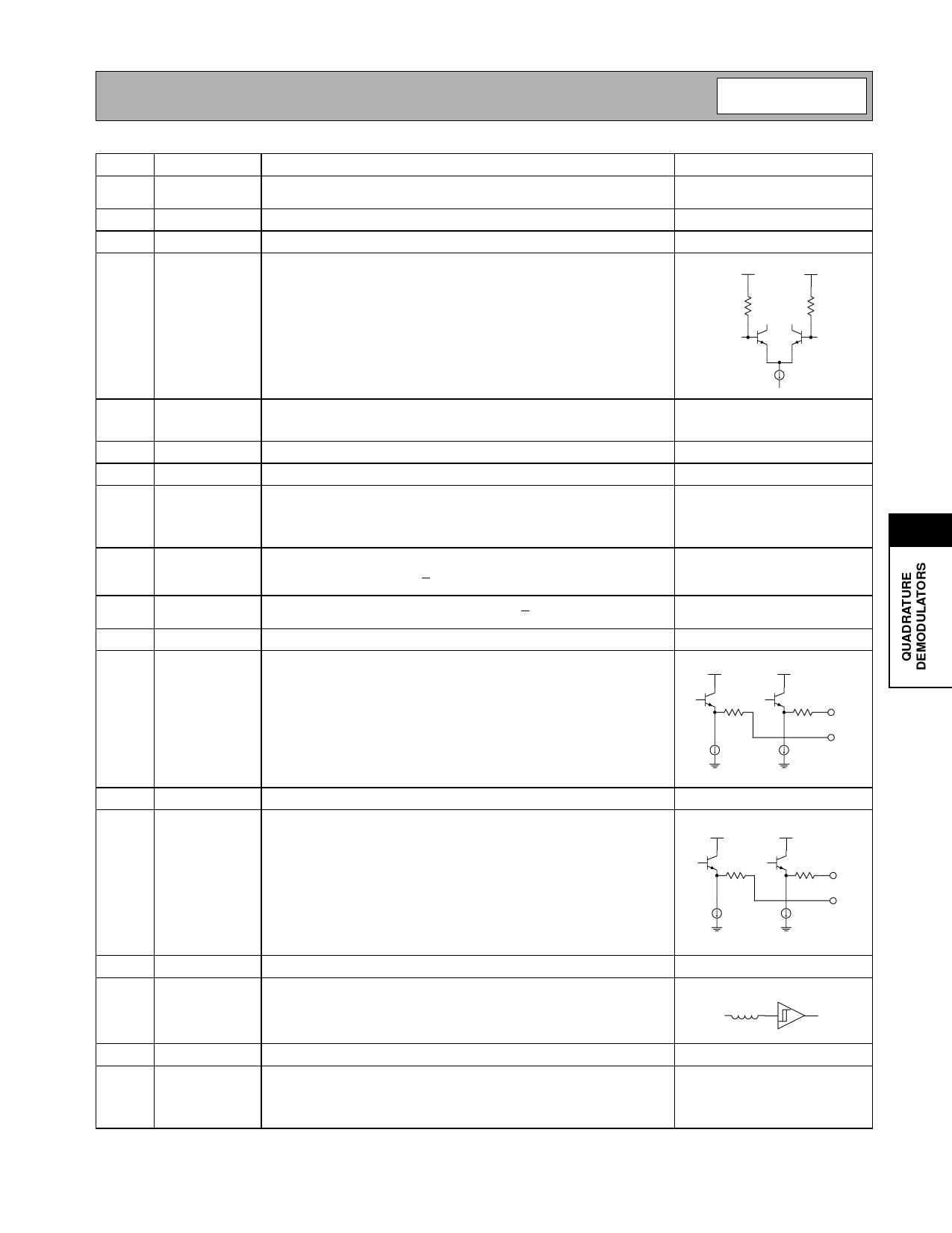
Pin
1
2
3
4
Function
VGC1
NC
NC
W-CDMA
IN+
Description
Interface Schematic
Analog gain control. Valid control voltage ranges are from 0.5V to 2.5V.
These voltages are valid with a 10kΩ resistor in series with GC pin.
Unused. Connect to signal ground in application.
Unused. Connect to signal ground in application.
W-CDMA balanced input pin. This pin is internally DC-biased and
should be DC-blocked if connected to a device with a DC level present.
For single-ended input operation, one pin is used as an input and the
other W-CDMA input is AC coupled to ground. The balanced input
impedance is 2.4kΩ, while the single-ended input impedance is 1.2kΩ.
BIAS
1200 Ω
W-CDMA IN+
BIAS
1200 Ω
W-CDMA IN-
5
W-CDMA Same as pin 4, except complementary input.
IN-
See pin 4.
6
VCC
Supply
7
GND
Connect to ground.
8
LO
LO input pin. This input is internally DC-biased and should be DC-
blocked if connected to a device with DC present. The frequency of the
signal applied to this pin is internally divided by a factor of four, hence
the LO applied should be four times the frequency of the IF.
9
EN WUP Warm-up mode enable. The input LO buffers and divider chains are
enabled. When logic “low” (<0.5V), chip is in warm-up mode. When
logic “high” (VCC -0.3V), chip is in W-CDMA RX mode.
10
EN RX
Chip enable. Power down. When logic “low” (<0.5V), all circuits are
turned off. When logic “high” (VCC -0.3V), all circuits are operating.
11
Q OUT- Complementary output to Q OUT+.
12
Q OUT+ Balanced baseband output of Q mixer. This pin is internally DC-biased
and should be DC-blocked externally. The output may be used single-
VCC
VCC
ended by leaving one of the pins unconnected, however half of the out-
put voltage will be lost.
150 µA
150 µA
13
I OUT-
Complementary output to I OUT+.
14
I OUT+ Balanced baseband output.
VCC
VCC
150 µA
150 µA
15
ENCAL Calibration enable.
16
FCLK
FCLK clock reference for the automatic calibration circuitry.
20 kΩ
17
IF-
Complementary output to IF+.
18
IF+
IF test point output. This balanced node is pinned out to allow for moni-
toring of the AGC output signal as it enters the demodulator. During
normal operation, this pin and its complementary output should be left
floating and not connected.
Rev A4 010918
7
Q OUT+
Q OUT-
I OUT+
I OUT-
7-43
Share Link: 