BQ24075RGTRG4 查看數據表(PDF) - Teccor Electronics
零件编号
产品描述 (功能)
比赛名单
BQ24075RGTRG4
Teccor Electronics

BQ24075RGTRG4 Datasheet PDF : 53 Pages
| |||
bq24072, bq24073, bq24074, bq24075, bq24079
SLUS810L – SEPTEMBER 2008 – REVISED JUNE 2018
www.ti.com
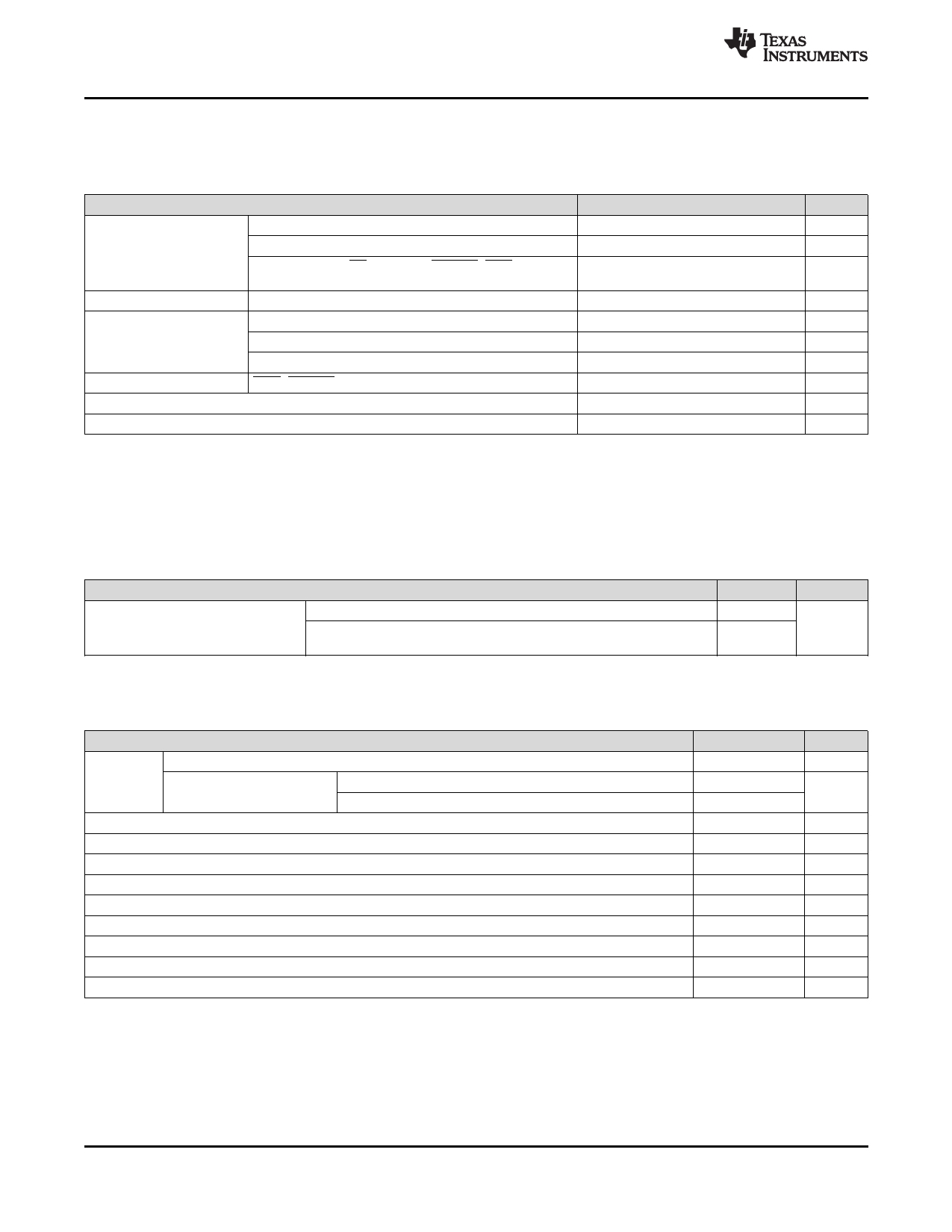
8 Specifications
8.1 Absolute Maximum Ratings(1)
over the 0°C to 125°C operating free-air temperature range (unless otherwise noted)
MIN
IN (with respect to VSS)
–0.3
VI Input Voltage
BAT (with respect to VSS)
–0.3
OUT, EN1, EN2, CE, TS, ISET, PGOOD, CHG, ILIM,
TMR, ITERM, SYSOFF, TD (with respect to VSS)
–0.3
II
Input Current
IO
Output Current
(Continuous)
IN
OUT
BAT (Discharge mode)
BAT (Charging mode)
Output Sink Current CHG, PGOOD
TJ Junction temperature
–40
Tstg Storage temperature
–65
MAX
28
5
7
1.6
5
5
1.5 (2)
15
150
150
UNIT
V
V
V
A
A
A
A
mA
°C
°C
(1) Stresses beyond those listed under Absolute Maximum Ratings may cause permanent damage to the device. These are stress ratings
only, and functional operation of the device at these or any other conditions beyond those indicated under Recommended Operating
Conditions is not implied. Exposure to absolute-maximum-rated conditions for extended periods may affect device reliability. All voltage
values are with respect to the network ground terminal unless otherwise noted.
(2) The IC operational charging life is reduced to 20,000 hours, when charging at 1.5A and 125°C. The thermal regulation feature reduces
charge current if the IC’s junction temperature reaches 125°C; thus without a good thermal design the maximum programmed charge
current may not be reached.
8.2 ESD Ratings
V(ESD) Electrostatic discharge
Human body model (HBM), per ANSI/ESDA/JEDEC JS-001(1)
Charged-device model (CDM), per JEDEC specification JESD22-
C101 (2)
VALUE
±2000
±500
(1) JEDEC document JEP155 states that 500-V HBM allows safe manufacturing with a standard ESD control process.
(2) JEDEC document JEP157 states that 250-V CDM allows safe manufacturing with a standard ESD control process.
UNIT
V
8.3 Recommended Operating Conditions
MIN MAX UNIT
IN voltage range
4.35
26 V
VI
’72, ’73, ‘75, '79
IN operating voltage range
‘74
4.35
6.4
V
4.35 10.2
IIN
IOUT
IBAT
ICHG
TJ
RILIM
RISET
RITERM
RTMR
Input current, IN pin
Current, OUT pin
Current, BAT pin (Discharging)
Current, BAT pin (Charging)
Junction Temperature
Maximum input current programming resistor
Fast-charge current programming resistor (2)
Termination current programming resistor
Timer programming resistor
1.5 A
4.5 A
4.5 A
1.5 (1)
A
–40
125 °C
1100 8000 Ω
590 8900 Ω
0
15 kΩ
18
72 kΩ
(1) The IC operational charging life is reduced to 20,000 hours, when charging at 1.5A and 125°C. The thermal regulation feature reduces
charge current if the IC’s junction temperature reaches 125°C; thus without a good thermal design the maximum programmed charge
current may not be reached.
(2) Use a 1% tolerance resistor for RISET to avoid issues with the RISET short test when using the maximum charge current setting.
8
Submit Documentation Feedback
Copyright © 2008–2018, Texas Instruments Incorporated
Product Folder Links: bq24072 bq24073 bq24074 bq24075 bq24079
Share Link: