AIC3842CN 查看數據表(PDF) - Analog Intergrations
零件编号
产品描述 (功能)
比赛名单
AIC3842CN Datasheet PDF : 7 Pages
| |||
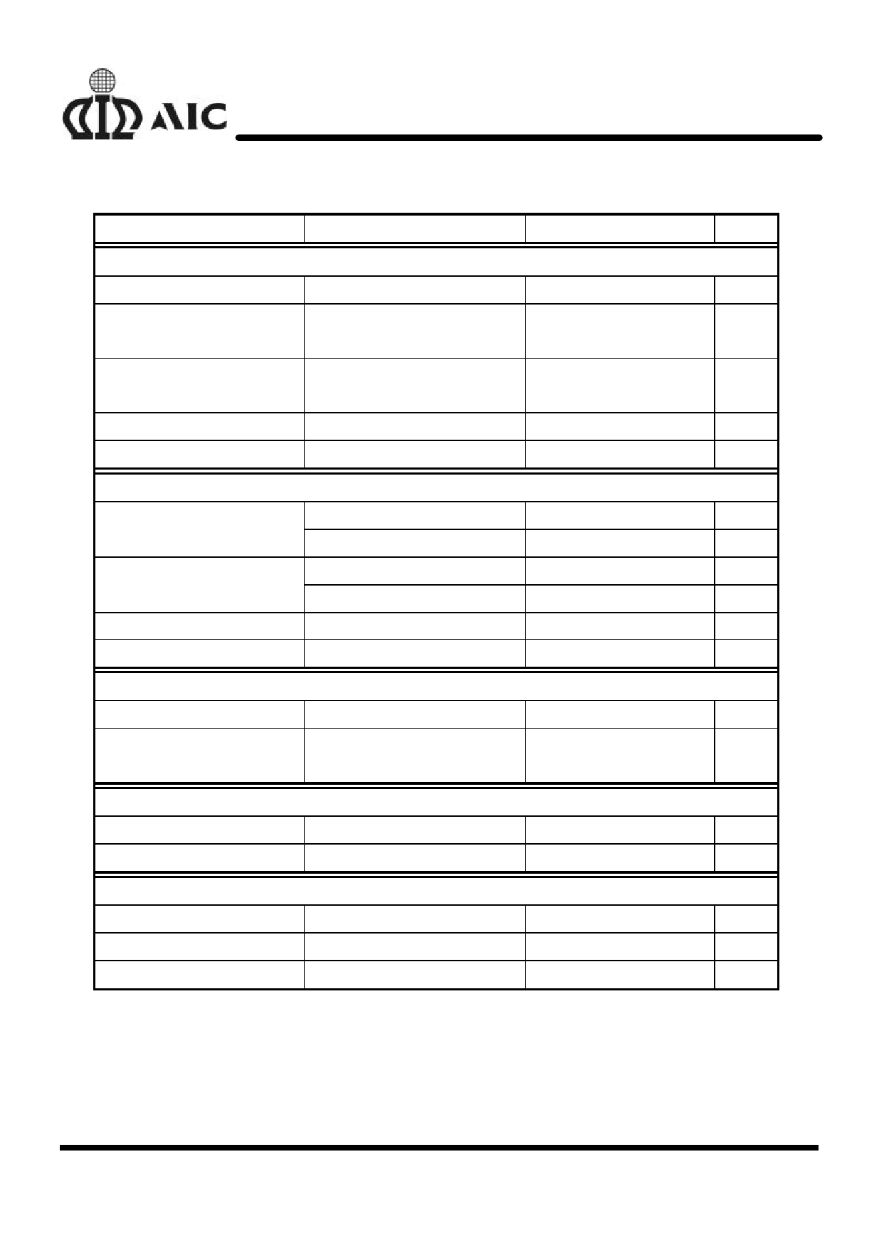
AIC3842
n ELECTRICAL CHARACTERISTICS (Continued)
PARAMETERS
CONDITIONS
MIN. TYP. MAX. UNIT
Current Sense Section
Voltage Amplification
See Note 3 and 4
3
V/V
Current Sense Comparator COMP at 5V, See Note 3
1
V
Threshold
Supply Voltage Rejection
VCC=12V to 25V, See Note 3
70
dB
Ratio
Input Bias Current
-2
µA
Delay Time to Output
150
nS
Output Section
High-Level Output Voltage
Low-Level Output Voltage
Rise Time
Fall Time
ISOURCE=20mA
ISOURCE =200mA
ISINK=20mA
ISINK=200mA
CL=1nF
CL=1nF
Undervoltage Lockout Section
Start Threshold Voltage
Minimum Operating Voltage
after Start-Up
13.5
V
13.4
V
0.1
V
1.5
V
50
nS
50
nS
14.5
16
17.5
V
8.5
10
11.5
V
Pulse-Width-Modulator Section
Maximum Duty Cycle
Minimum Duty Cycle
96
%
0
%
Supply Voltage
Start-Up Current
0.3
0.5
mA
Operating Supply Current
VFB and ISENSE at 0V
12
17
mA
Limiting Voltage
ICC=25mA
34
V
Note: 2: Adjust VCC above the start threshold before setting it to 15V.
3. These parameters are measured at the trip point of the latch with VFB at 0V.
4. Voltage amplification is measured between ISENSE and COMP with the input changing from 0V to
0.8V.
4
Share Link: 