MAX1573 查看數據表(PDF) - Maxim Integrated
零件编号
产品描述 (功能)
比赛名单
MAX1573 Datasheet PDF : 9 Pages
| |||
White LED 1x/1.5x Charge Pump in
UCSP and Thin QFN
True Shutdown™ Mode
When EN1 and EN2 are grounded, the MAX1573 is in
shutdown, and the charge pump examines whether the
input voltage is greater than or less than the output volt-
age and shorts the transfer capacitor nodes to either IN
or OUT as necessary. The output is high impedance in
either case.
Thermal Shutdown
The MAX1573 includes a thermal-limit circuit that shuts
down the IC at about +160°C. Turn-on occurs after the
IC cools by approximately 20°C.
Setting the Output Current
SET controls the LED bias current. Current flowing into
LED1, LED2, LED3, and LED4 is a multiple of the current
flowing out of SET. Set the output current as follows:
ILED _
=
K
x
⎛ 0.6V ⎞
⎝⎜ RSET ⎠⎟
where K = 22, 66, or 219 (depending upon EN1 and
EN2, see Table 1), and RSET is the resistor connected
between SET and GND (see the Typical Operating
Circuit).
Table 1. EN1/EN2 States
EN1/EN2 STATES
EN1 = low, EN2 = low
EN1 = low, EN2 = high
EN1 = high, EN2 = low
EN1 = high, EN2 = high
BRIGHTNESS
Shutdown
1/10 Brightness
3/10 Brightness
Full Brightness
LED CURRENT
ILED = 0
ILED = 22 x ISET
ILED = 66 x ISET
ILED = 219 x ISET
True Shutdown is a trademark of Maxim Integrated Products, Inc.
Applications Information
Dimming Using EN1 and EN2
Use EN1 and EN2 inputs as a digital 2-bit number to
control on/off, 1/10, 3/10, and full current (see Table 1).
RSET programs the full current level (see the Setting the
Output Current section).
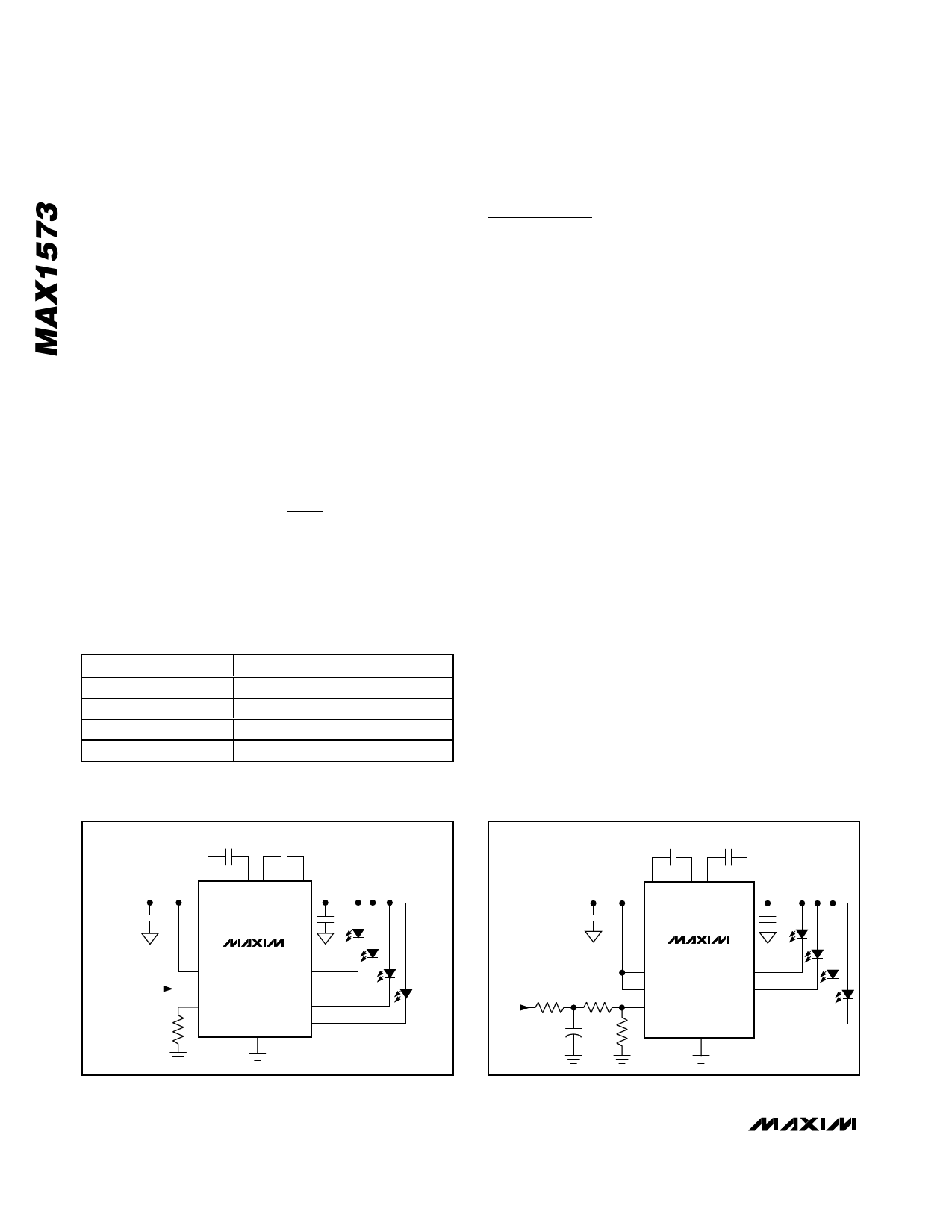
Dimming Using PWM into EN1
Use EN2 for shutdown and drive EN1 with a PWM sig-
nal. Current can be varied from 1/10 to full. The wave-
forms in the Typical Operating Characteristics show the
response time of dimming. EN2 keeps the part on, elimi-
nating any soft-start delay that would impede PWM con-
trol, allowing a PWM frequency up to 50kHz (Figure 1).
Dimming Using a Filtered PWM Signal
Use a high-frequency PWM signal to drive an R-C-R fil-
ter on the SET pin (Figure 2). A 0% PWM duty cycle
corresponds to 18.7mA/LED, while a 100% PWM duty
cycle corresponds to 0mA/LED. At PWM frequencies
above 5kHz, C3 may be reduced.
Input Ripple
For LED drivers, input ripple is more important than out-
put ripple. Input ripple depends on the source supply’s
impedance. Adding a lowpass filter to the input further
reduces input ripple. Figure 3 shows a C-R-C filter used
to reduce input ripple to less than 2mVP-P when driving
a 75mA load. Alternately, increasing CIN to 2.2µF or
4.7µF yields input ripple of 17mVP-P or 9mVP-P, respec-
tively, with only a small increase in footprint. The 1x
mode always has very low input ripple.
1μF
1μF
C1P C1N C2P C2N
IN
VIN
1μF
OUT
1μF
MAX1573
EN2
LED1
PWM INPUT
EN1
LED2
SET
LED3
LED4
RSET
GND
1μF
1μF
C1P C1N C2P C2N
IN
VIN
1μF
OUT 0 TO 18.7mA/LED
1μF
MAX1573
EN1
LED1
PWM
INPUT
0 TO
2.5V
R1
14.3kΩ
C3
1μF
R2
EN2
14.3kΩ SET
RSET
9.09kΩ
LED2
LED3
LED4
GND
Figure 1. Dimming Using PWM Signal into EN1
Figure 2. Dimming Using Filtered PWM Signal
6 _______________________________________________________________________________________
Share Link: 