MAX6711S 查看數據表(PDF) - Maxim Integrated
零件编号
产品描述 (功能)
比赛名单
MAX6711S Datasheet PDF : 8 Pages
| |||
4-Pin SC70 Microprocessor Reset Circuits
with Manual Reset Input
_____________________Pin Description
PIN NAME
1
GND
RESET
(MAX6711/
MAX6713)
2
RESET
(MAX6712)
3
MR
4
VCC
FUNCTION
Ground
RESET output remains low while VCC
is below the reset threshold, and for at
least 140ms after VCC rises above the
reset threshold.
RESET output remains high while VCC
is below the reset threshold, and for at
least 140ms after VCC rises above the
reset threshold.
Manual Reset Input. RESET (RESET)
remains asserted as long as MR is low,
and for at least 140ms after MR is
deasserted. This active-low input has
an internal 20kΩ (typ) pull-up resistor.
It can be driven from a TTL- or CMOS-
logic line, or shorted to ground with a
switch. Leave open or connect to VCC
if unused.
Supply Voltage (+5.0V, +3.3V, +3.0V,
or +2.5V)
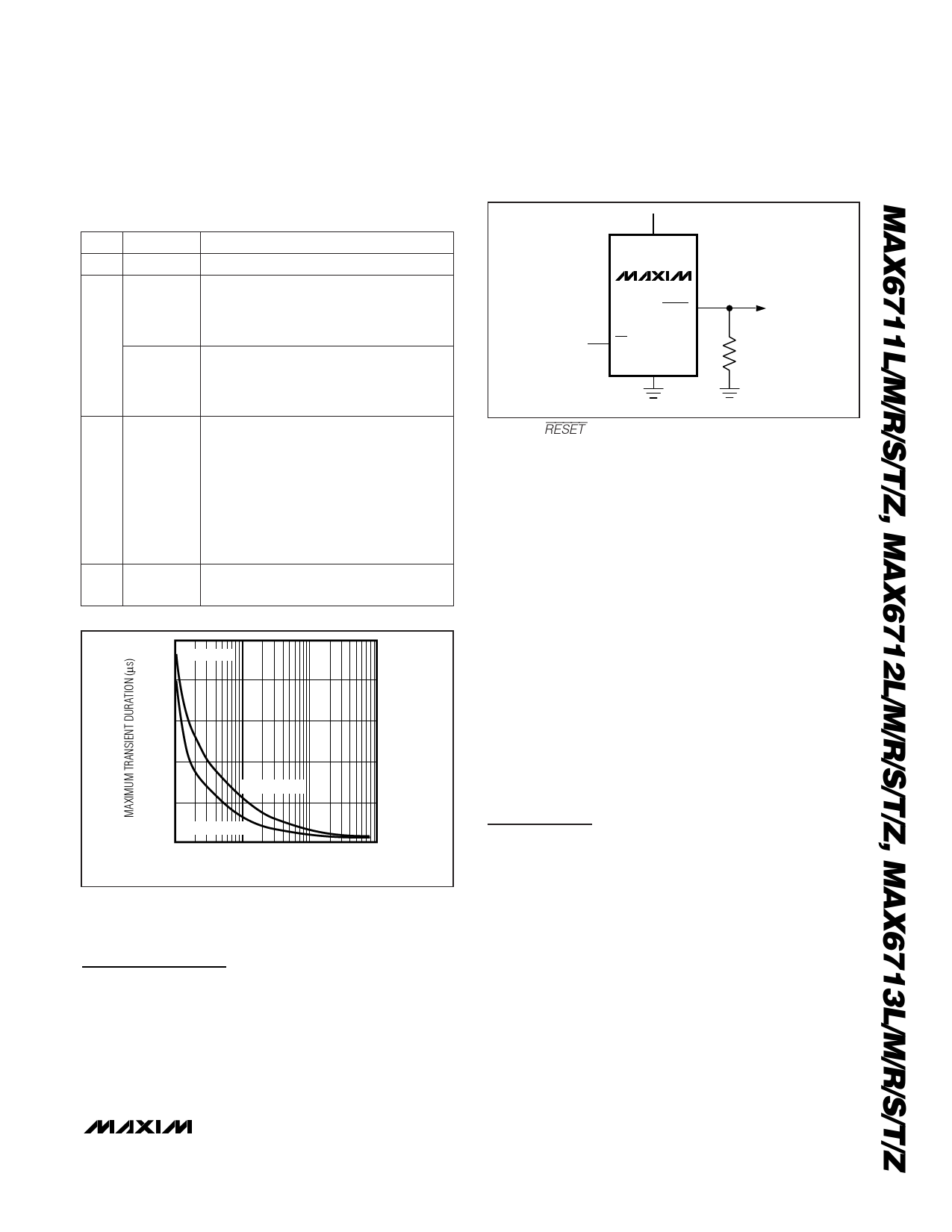
400
TA = +25°C
320
240
160
MAX671_L/M
80
MAX671_R/S/T/Z
0
1
10
100
1000
RESET COMPARATOR OVERDRIVE, VTH - VCC (mV)
Figure 1. Maximum Transient Duration Without Causing a
Reset Pulse vs. Reset Comparator Overdrive
Detailed Description
Reset Output
A microprocessor’s (µP’s) reset input starts the µP in a
known state. The MAX6711/MAX6712/MAX6713 assert
reset to prevent code-execution errors during power-
up, power-down, or brownout conditions. They assert a
reset signal whenever the VCC supply voltage declines
below a preset threshold, keeping it asserted for at
VCC
MAX6711
RESET
MR
R1
GND
100k
Figure 2. RESET Valid to VCC = Ground Circuit
least 140ms after VCC has risen above the reset thresh-
old. The MAX6713 uses an open-drain output, and the
MAX6711/MAX6712 have a push-pull output stage.
Connect a pull-up resistor on the MAX6713’s RESET
output to any supply between 0 and 6V.
Manual Reset Input
Many µP-based systems require manual reset capabili-
ty, allowing the operator, a test technician, or external
logic circuitry to initiate a reset. Reset remains asserted
while MR is low, and for at least 140ms after MR returns
high. This input has an internal 20kΩ pullup resistor, so
it can be left open if it is not used. MR can be driven
with TTL- or CMOS-logic levels, or with open-drain/col-
lector outputs. To create a manual reset function, con-
nect a normally open momentary switch from MR to
ground; external debounce circuitry is not required. If
MR is driven from long cables or if the device is used in
a noisy environment, connecting a 0.1µF capacitor from
MR to ground provides additional noise immunity.
Applications Information
Negative-Going VCC Transients
In addition to issuing a reset to the µP during power-up,
power-down, and brownout conditions, the MAX6711/
MAX6712/MAX6713 are relatively immune to short-dura-
tion negative-going VCC transients (glitches).
Figure 1 shows typical transient duration vs. reset com-
parator overdrive, for which the MAX6711/MAX6712/
MAX6713 do not generate a reset pulse. The graph was
generated using a negative-going pulse applied to VCC,
starting 0.5V above the actual reset threshold and end-
ing below it by the magnitude indicated (reset compara-
tor overdrive). The graph indicates the maximum pulse
width a negative-going VCC transient can have without
causing a reset pulse. As the magnitude of the transient
increases (goes farther below the reset threshold), the
_______________________________________________________________________________________ 5
Share Link: 