MX10FMAXDPC 查看數據表(PDF) - Macronix International
零件编号
产品描述 (功能)
比赛名单
MX10FMAXDPC Datasheet PDF : 24 Pages
| |||
MX10FMAXDPC
MX10FMAXDQC
NOTES:
1. Capacitive loading on Ports 0 and 2 may cause noise pulses above 0.4V to be superimposed on the VOLs of ALE and Ports 1, 2 and 3. The
noise is due to external bus capacitance discharging into the Port 0 and Port 2 pins when these pins change from 1 to 0. In applications
where capacitive loading exceeds 100 pF, the noise pulses on these signlas may exceed 0.8V. It may be desirable to qualify ALE or other
signals with a Schmitt Triggers, or CMOS-level input logic.
2. Capacitive loading on Ports 0 and 2 cause the VOH on ALE and PSEN to drop below the 0.9 VCC specification when the address lines are
stabilizing.
3. Minimum VCC for Power Down is 2V.
4. Typicals are based on a limited number of samples and are not guaranteed. The values listed are room temperature and 5V.
5. Under steady state (non-transient) conditions, IOL must be externally limited as follows:
Maximum IOL per port pin:
10mA
Maximum IOL per 8-bit port:
Port 0:
26mA
Ports 1, 2 and 3: 15mA
Maximum total IOL for all output pins:
71mA
If IOL exceeds the test condition, VOL may exceed the related specification. Pins are not guaranteed to sink current greater than the listed test
conditions.
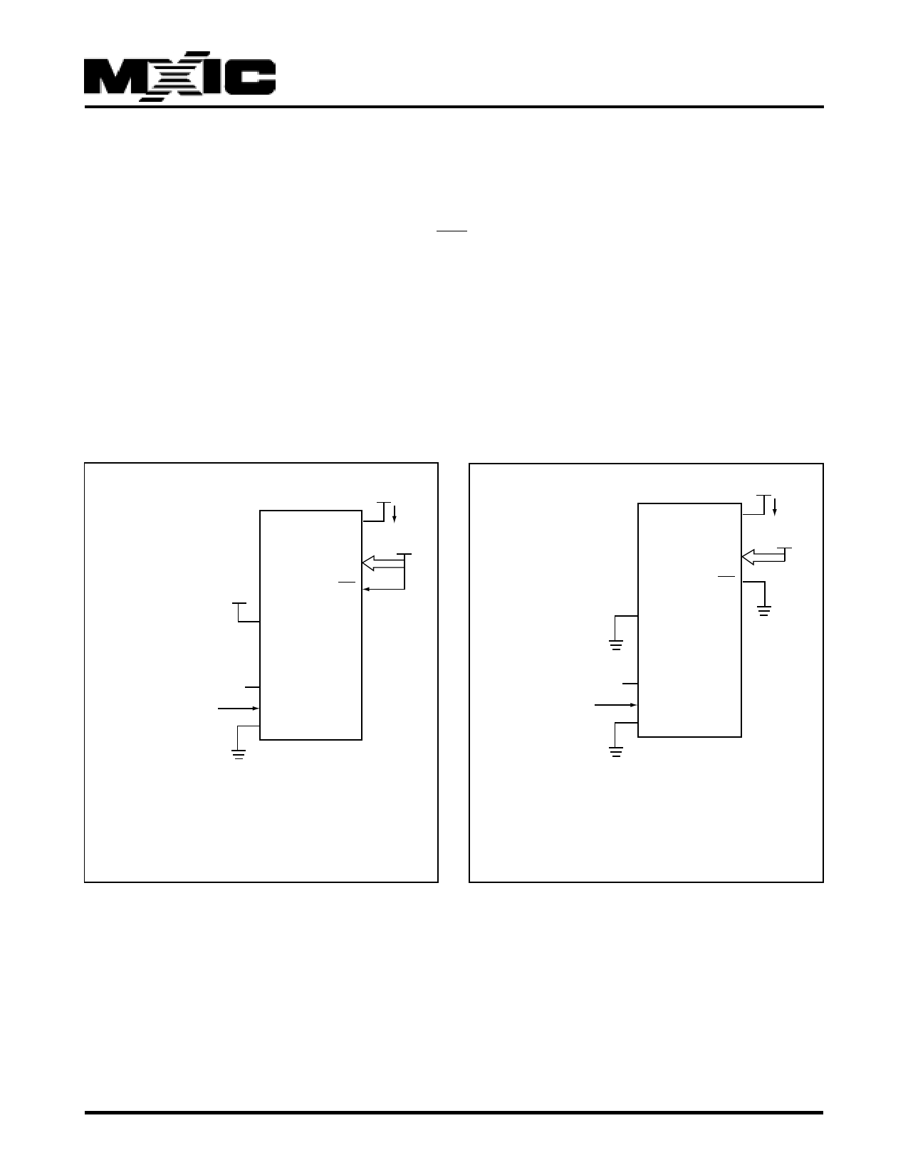
VCC
VCC
VCC
P0
ICC
VCC
EA
RST
MX10FMAX
(NC)
CLOCK
SIGNAL
XTAL2
XTAL1
VSS
VCC
VCC
P0
ICC
VCC
EA
RST
MX10FMAX
(NC)
CLOCK
SIGNAL
XTAL2
XTAL1
VSS
All other pins disconnected
TCLCH = TCHCL = 5ns
Figure 6. ICC Test Condition, Active Mode
All other pins disconnected
TCLCH = TCHCL = 5ns
Figure 7. ICC Test Condition Idle Mode
P/N:PM1053 Specifications subject to change without notice, contact your sales representatives for the most update information. REV. 1.0, DEC. 10, 2003
16
Share Link: 