AIC2511-50PM5TB 查看數據表(PDF) - Analog Intergrations
零件编号
产品描述 (功能)
比赛名单
AIC2511-50PM5TB Datasheet PDF : 13 Pages
| |||
AIC2511
APPLICATION INFORMATION (Continued)
Components Selection
Assume the input voltage is 12V, output voltage is
5V and maximum load current is 3A. The output
Inductor
ripple must be smaller than 2% of output voltage
The inductor selection depends on the operating
frequency of the AIC2511. The ripple current ∆IL
interrelates with inductor value. A lower inductor
value gets a higher ripple current. Besides, a
higher VIN or VOUT can also get the same result.
The inductor value can be calculated as the
Inductor selection
L
=
(f
1
)(∆I L )VOUT
⎜⎜⎝⎛1 −
VOUT
VIN
⎟⎟⎠⎞
= 1 × 5 × ⎜⎛1 − 5 ⎟⎞ = 32.4uH
150k × 0.6 ⎝ 12 ⎠
following formula.
L
=
1
(f )(∆IL
)
VOUT ⎜⎜⎝⎛1−
VOUT
VIN
⎟⎟⎠⎞
Here, the delta IL is 0.6A. So we choose 33uH
inductor.
Users can define the acceptable ∆IL to gain a
suitable inductor value.
Diode
The diode current rating must be higher than 1.3
times maximum load current. Also, if the power
supply needs to resist a continuous output short,
the diode should have a current ration equal to the
maximum current limit of the AIC2511. The
reverse voltage rating of the diode should be
higher than 1.25 times input voltage and the diode
must be fast. The reverse recovery time of the
diode is short.
Capacitor
The selection of output capacitor depends on the
suitable ripple voltage. Lower ripple voltage
corresponds to lower ESR (Equivalent Series
Resistor) of output capacitor. Typically, once the
ESR is satisfied with the ripple voltage, the value
of capacitor is adequate for filtering. The formula
of ripple voltage is as below:
∆VOUT
=
∆IL ⎜⎜⎝⎛ESR +
1
8fCOUT
⎟⎟⎠⎞
The typical input capacitor is 470uF. But as the
temperature decreases, the input capacitor needs
to increase to stabilize the circuit.
Output capacitor selection
∆VOUT
=
∆I
L
⎜⎜⎝⎛
ESR
+
8
1
fCOUT
⎟⎟⎠⎞ < 100mV
We choice the capacitor value: ESR=0.12,
capacitance=220uF
⇒
∆VOUT
=
∆I L
⎜⎜⎝⎛ ESR+
8
1
fCOUT
⎟⎟⎠⎞
=
74mV
< 100mV
The full load is 3A and delta IL is 0.6A, so the
diode current rating must be higher than 3.6A.
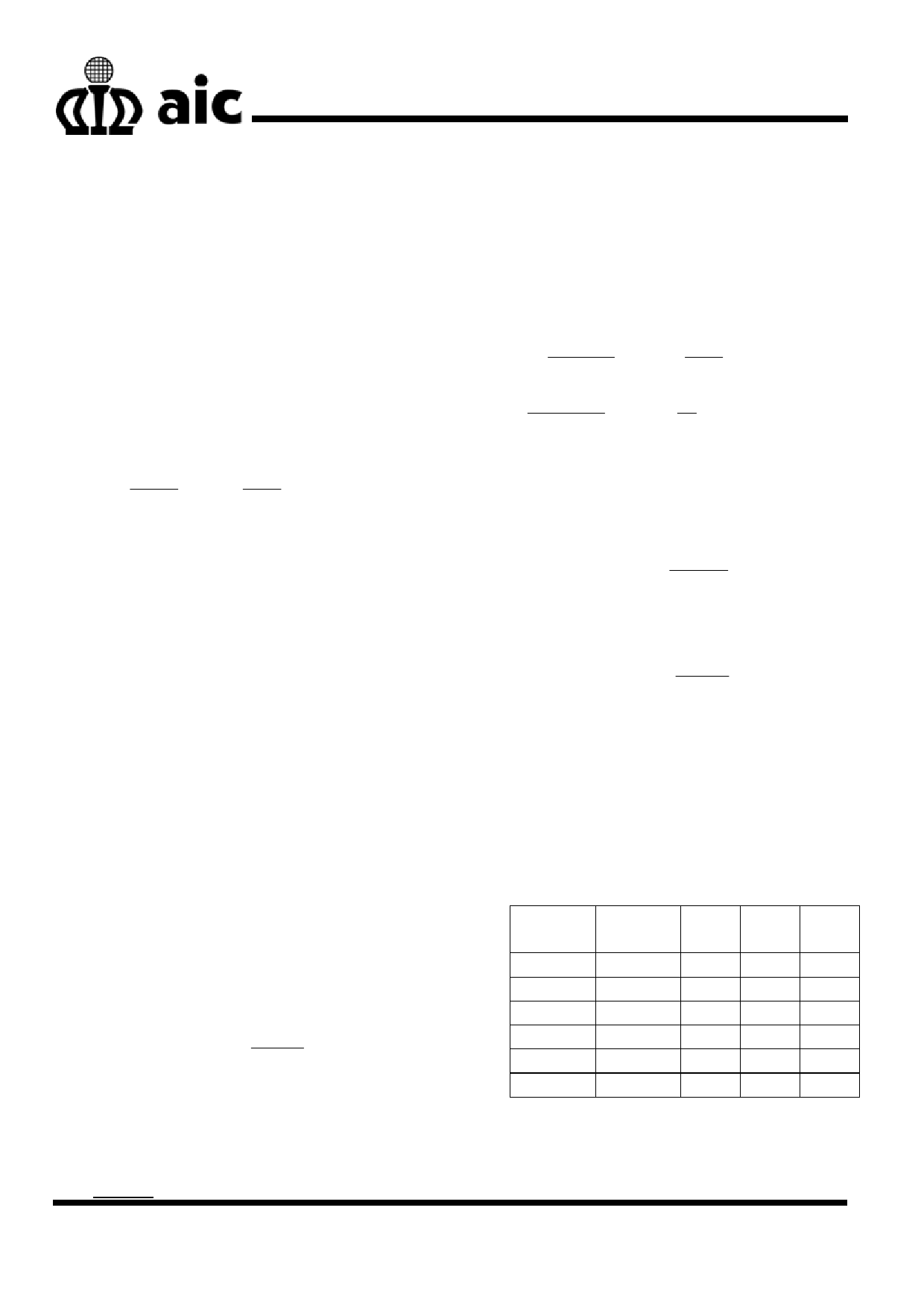
CF Capacitor for adj version
As using the AIC2511 adj version, the CF
capacitor is required to provide additional stability.
In different condition, the CF capacitor must be
changed to make the circuit stable.
Output
Input
R1 R2 CF
Voltage (V) Voltage (V) (Ω) (Ω) (pF)
1.8
7
36k 82k 1000
4
12
180k 82k 360
6
12
180k 47k 360
8
15
180k 33k 360
10
18
150k 22k 470
15
25
110k 10k 560
Table 1
Example
9
Share Link: 