MAX8631X(2006) 查看數據表(PDF) - Maxim Integrated
零件编号
产品描述 (功能)
比赛名单
MAX8631X
(Rev.:2006)
(Rev.:2006)
Maxim Integrated

MAX8631X Datasheet PDF : 16 Pages
| |||
1x/1.5x/2x White LED Charge Pump with Two
LDOs in 4mm x 4mm Thin QFN
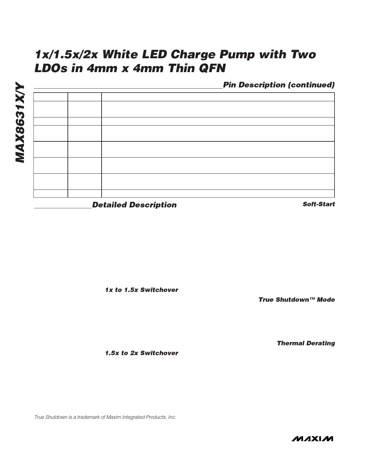
Pin Description (continued)
PIN
NAME
FUNCTION
23
C1P
Transfer Capacitor 1 Positive Connection. Connect a 1µF ceramic capacitor between C1P to C1N.
During shutdown, if OUT > IN, C1P is shorted to OUT. If OUT < IN, C1P is shorted to IN.
24
PGND Power Ground. Connect PGND to system ground. PGND is used for charge-pump switching currents.
25
OUT
Charge-Pump Output. Bypass OUT to GND with a 10µF ceramic capacitor. Connect to the anodes of
all the LEDs. OUT is internally pulled to ground through a 5kΩ resistor during shutdown.
26
C2P
Transfer Capacitor 2 Positive Connection. Connect a 1µF ceramic capacitor between C2P to C2N.
During shutdown, if OUT > IN, C2P is shorted to OUT. If OUT < IN, C2P is shorted to IN.
27
C2N
Transfer Capacitor 2 Negative Connection. Connect a 1µF ceramic capacitor between C2P and C2N.
C2N is internally shorted to IN during shutdown.
28
P1
Default Output-Voltage Select Input. P1 and P2 set the LDO1 and LDO2 voltages to one of nine
combinations (Table 2). P1 is high impedance in an off condition and shortly after an on condition.
—
EP
Exposed Paddle. Connect to GND and PGND.
Detailed Description
The MAX8631X/Y charge pump drives up to 4 white
LEDs in the main display for backlighting and up to 4
white LEDs for flash, all with regulated constant current
for uniform intensity. By utilizing adaptive 1x/1.5x/2x
charge-pump modes and very-low-dropout current reg-
ulators, it achieves high efficiency over the 1-cell lithi-
um-battery input voltage range. 1MHz fixed-frequency
switching allows for tiny external components and low
input ripple. Two on-board 200mA programmable-out-
put-voltage LDOs are provided to meet camera-module
requirements.
1x to 1.5x Switchover
When VIN is higher than VOUT, the MAX8631X/Y oper-
ates in 1x mode and VOUT is pulled up to VIN. The
internal current regulators regulate the LED current. As
VIN drops, VM_ (or VF_) eventually falls below the
switchover threshold of 100mV and the MAX8631X/Y
starts switching in 1.5x mode. When the input voltage
rises above VOUT by approximately 50mV, the
MAX8631X/Y switches back to 1x mode.
1.5x to 2x Switchover
When VIN is less than VOUT but greater than two-thirds
VOUT, the MAX8631X/Y operates in 1.5x mode. The
internal current regulators regulate the LED current. As
VIN drops, VM_ (or VF_) eventually falls below the
switchover threshold of 100mV, and the MAX8631X/Y
starts switching in 2x mode. When the input voltage
rises above two-thirds VOUT by approximately 50mV,
the MAX8631X/Y switches back to 1.5x mode.
True Shutdown is a trademark of Maxim Integrated Products, Inc.
Soft-Start
The MAX8631X/Y includes soft-start circuitry to limit
inrush current at turn-on. Once the input voltage is
applied, the output capacitor is charged directly from
the input with a ramped current source (with no charge-
pump action) until the output voltage approaches the
input voltage. Once the output capacitor is charged,
the charge pump determines if 1x, 1.5x, or 2x mode is
required. In the case of 1x mode, the soft-start is termi-
nated and normal operation begins. In the case of 1.5x
or 2x mode, soft-start operates until the lowest voltage
of M1–M4 and F1–F4 reaches regulation. If the output is
shorted to ground or is pulled to less than 1.25V, the
output current is limited by soft-start.
True Shutdown™ Mode
When ENM1, ENM2, and ENF are simultaneously held
low for 2ms or longer, the MAX8631X/Y is shut down
and put in a low-current shutdown mode, and the input
is isolated from the output. OUT is internally pulled to
GND with 5kΩ during shutdown.
Thermal Derating
The MAX8631X/Y limits the maximum LED current
depending on the die temperature. The maximum LED
current is set by the RSETM and RSETF resistors. Once
the temperature reaches +43°C, the LED current
decreases by 1.7%/°C. Due to the package’s exposed
paddle, the die temperature is always very close to the
PC board temperature.
The temperature derating function allows the LED cur-
rent to be safely set higher at normal operating temper-
atures, thereby allowing either a brighter display or
fewer LEDs to be used for normal display brightness.
10 ______________________________________________________________________________________
Share Link: