MAX8631YETI(2006) 查看數據表(PDF) - Maxim Integrated
零件编号
产品描述 (功能)
比赛名单
MAX8631YETI
(Rev.:2006)
(Rev.:2006)
Maxim Integrated

MAX8631YETI Datasheet PDF : 16 Pages
| |||
1x/1.5x/2x White LED Charge Pump with Two
LDOs in 4mm x 4mm Thin QFN
INITIAL tHI
0
≥ 200µs
1
23
45
ENM1 AND ENM2
OR
ENF
IM_ OR IF_
tSOFT-START
32/32
31/32
30/32
tLO
500ns TO 250µs
29/32 28/32 27/32
SHUTDOWN
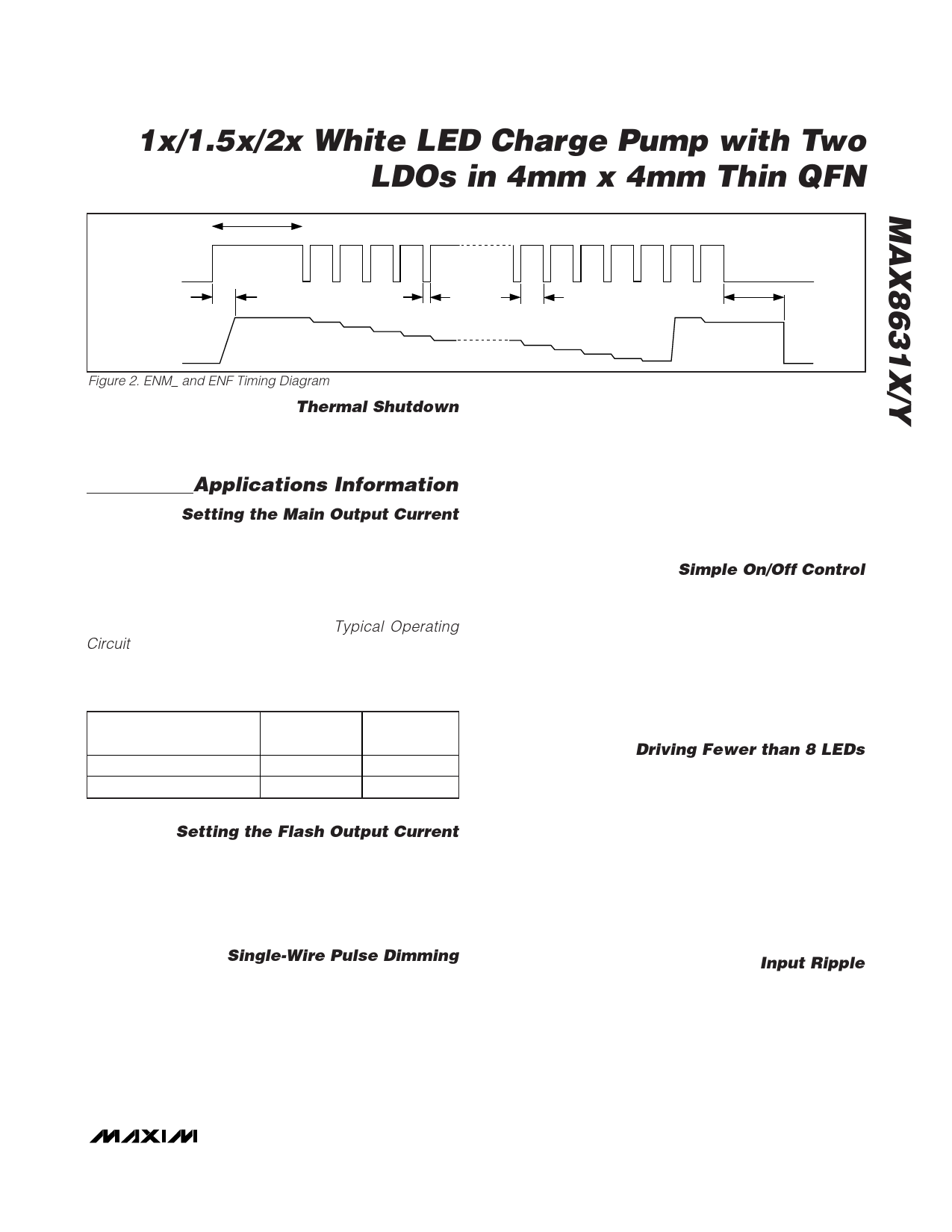
Figure 2. ENM_ and ENF Timing Diagram
Thermal Shutdown
The MAX8631X/Y includes a thermal-limit circuit that
shuts down the IC at approximately +160°C. Turn-on
occurs after the IC cools by approximately 20°C.
Applications Information
Setting the Main Output Current
SETM controls M1–M4 regulation current. Current flow-
ing into M1, M2, M3, and M4 is a multiple of the current
flowing out of SETM:
IM1 = IM2 = IM3 = IM4 = K x (0.6V / RSETM)
where K = 23, 69, or 230 (depending upon the state of
ENM1 and ENM2; see Table 1), and RSETM is the resis-
tor connected between SETM and GND (see the
Typical Operating Circuit).
Table 1. ENM1/ENM2 States
ENM1/ENM2 STATES BRIGHTNESS
ENM1 = low, ENM2 = low
ENM1 = low, ENM2 = high
ENM1 = high, ENM2 = low
ENM1 = high, ENM2 = high
Shutdown
1/10 brightness
3/10 brightness
Full brightness
M1–M4
CURRENT
0
23 x ISETM
69 x ISETM
230 x ISETM
Setting the Flash Output Current
SETF controls the F1–F4 regulation current. Current
flowing into F1, F2, F3, and F4 is a multiple of the cur-
rent flowing out of SETF.
IF1 = IF2 = IF3 = IF4 = N x (0.6V / RSETF)
where N = 690.
Single-Wire Pulse Dimming
For more dimming flexibility or to reduce the number of
control traces, the MAX8631X/Y supports serial pulse
dimming. Connect ENM1 and ENM2 together to enable
single-wire pulse dimming of the main LEDs (or ENF
only for single-wire pulse dimming of the flash LEDs).
When ENM1 and ENM2 (or ENF) go high simultaneous-
27 28 29 30 31 32
tHI
≥500ns
tSHDN
32/32 31/32 2ms (typ)
5/32 4/32 3/32 2/32 1/32
SHUTDOWN
ly, the main (or flash) LEDs are enabled at full bright-
ness. Each subsequent low-going pulse (500ns to
250µs pulse width) reduces the LED current by 3.125%
(1/32), so after one pulse the LED current is 96.9% (or
31/32) x ILED. The 31st pulse reduces the current to
0.03125 x ILED. The 32nd pulse sets the LED current
back to ILED. Figure 2 shows a timing diagram for sin-
gle-wire pulse dimming. Because soft-start is longer
than the initial tHI, apply dimming pulses quickly upon
startup (after initial tHI) to avoid LED current transition-
ing through full brightness.
Simple On/Off Control
If dimming control is not required, connect ENM1 to
ENM2 for simple on/off control. Drive both ENM1 and
ENM2 to a logic-level high to turn on the main LEDs.
Drive both ENM1 and ENM2 to a logic-level low to turn
off the main LEDs. ENF is the simple on/off control for
the flash LEDs. Drive ENF to a logic-level high to turn
on the flash LEDs. Drive ENF to a logic-level low to turn
off the flash LEDs. In this case, LED current is set by
the values of RSETM and RSETF.
Dimming Using PWM into ENM1
Use ENM2 for shutdown and drive ENM1 with a PWM
signal. LED brightness can be varied from 10% to full
brightness based upon the duty cycle of the PWM sig-
nal. Drive ENM2 high to keep the IC on, eliminating any
soft-start delay that would impede PWM control and
allowing a PWM frequency up to 5kHz (Figure 3).
Driving Fewer than 8 LEDs
When driving fewer than 8 LEDs, two different connec-
tion schemes can be used. The first scheme is shown
in Figure 4 where LED drivers are connected together.
This method allows increased current through the LED
and effectively allows total LED current to be ILED multi-
plied by the number of connected drivers. The second
method of connection is shown in Figure 5 where stan-
dard white LEDs are used and fewer than 8 are con-
nected. This scheme does not alter current through
each LED but ensures that the unused LED driver is
properly disabled.
______________________________________________________________________________________ 11
Share Link: