MAX8630X 查看數據表(PDF) - Maxim Integrated
零件编号
产品描述 (功能)
比赛名单
MAX8630X Datasheet PDF : 12 Pages
| |||
125mA 1x/1.5x Charge Pumps for 5 White LEDs
in 3mm x 3mm TDFN
PIN
MAX8630X
MAX8630W
5
5
6
6
7
7
8
—
9
—
—
8
—
9
10
10
11
11
12
12
13
13
14
14
—
—
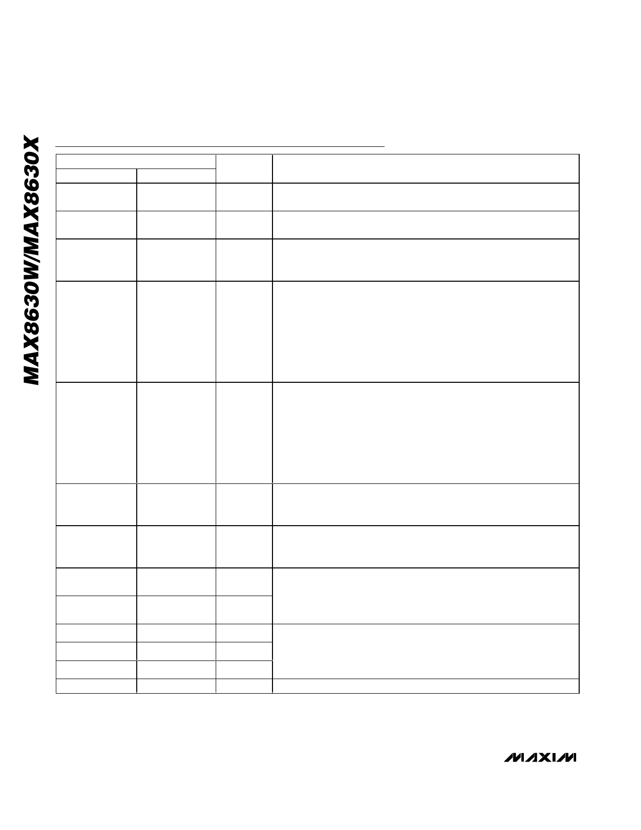
Pin Description (continued)
NAME
C 2P
C 1P
OUT
ENS
ENM
P WM
CPWM
LED5
LED4
LED3
LED2
LED1
EP
F U N C T IO N
Transfer Capacitor 2 Positive Connection. Connect a 1µF ceramic capacitor
from C2P to C2N.
Transfer Capacitor 1 Positive Connection. Connect a 1µF ceramic capacitor
from C1P to C1N.
Output. Connect a 1µF ceramic capacitor from OUT to GND. Connect OUT to
the anodes of all the LEDs. In shutdown, OUT is pulled down by an internal
5kΩ resistor.
Enable and Dimming Control for Sub LEDs (LED4 and LED5). Drive ENS logic-
low for greater than 4ms to disable the sub LEDs. Drive both ENM and ENS
logic-low for greater than 4ms to shut down the IC. Drive ENS logic-high to
begin soft-start and enable maximum (100%) sub LED current. Subsequent
pulses on ENS cause the sub LED current to decrease in 32 linear steps.
Because of the soft-start delay, it is possible to turn on the IC and quickly set a
dim level so the sub LED current never transitions through the maximum
setting. See the ENM/ENS Dimming Control section.
Enable and Dimming Control for Main LEDs (LED1, LED2, and LED3). Drive
ENM logic-low for greater than 4ms to disable the main LEDs. Drive both ENM
and ENS logic-low for greater than 4ms to shut down the IC. Drive ENM logic-
high to begin soft-start and enable maximum (100%) main LED current.
Subsequent pulses on ENM cause the main LED current to decrease in 32
linear steps. Because of the soft-start delay, it is possible to turn on the IC and
quickly set a dim level so the main LED current never transitions through the
maximum setting. See the ENM/ENS Dimming Control section.
Direct PWM input. PWM controls output current as a percentage of full-scale
current in proportion to PWM signal duty cycle. The frequency range is 900Hz
to 200kHz.
PWM Filter Capacitor Connection. Connect a capacitor from CPWM to GND to
form a filter with the internal 150kΩ resistor. The recommended capacitor for
10Hz corner is 0.1µF.
Sub LED Cathode Connections and Charge-Pump Feedback. Current flowing
into LED_ is based on the ENS (or PWM) description above. The charge pump
regulates the lowest LED_ voltage to 0.12V. Connect LED_ to OUT if the
corresponding LED is not populated.
Main LED Cathode Connections and Charge-Pump Feedback. Current flowing
into LED_ is based on the ENM (or PWM) description above. The charge pump
regulates the lowest LED_ voltage to 0.12V. Connect LED_ to OUT if the
corresponding LED is not populated.
Exposed Paddle. Connect to GND directly under the IC.
6 _______________________________________________________________________________________
Share Link: 