AS5040 查看數據表(PDF) - Unspecified
零件编号
产品描述 (功能)
比赛名单
AS5040 Datasheet PDF : 20 Pages
| |||
AS5040 10-BIT PROGRAMMABLE MAGNETIC ROTARY ENCODER
10 bit Absolute Angular Position Output
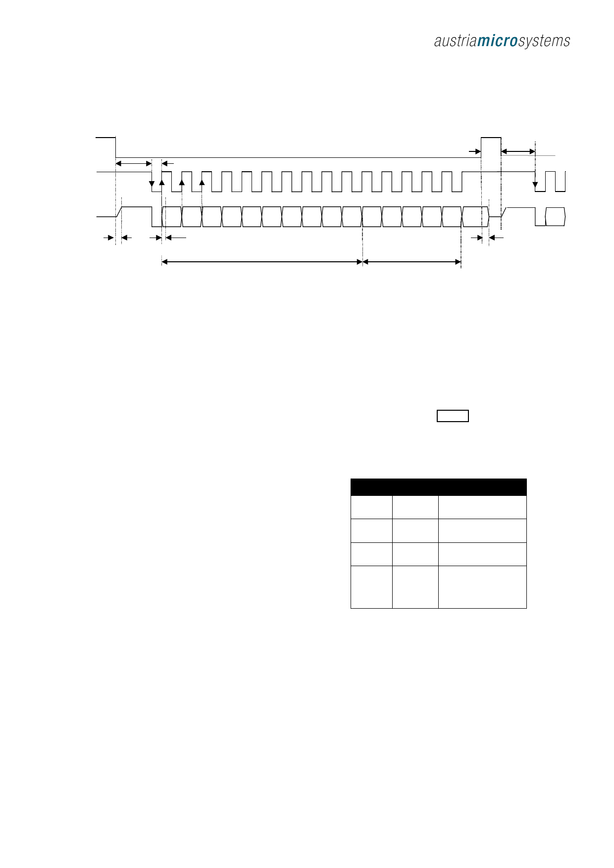
Synchronous Serial Interface SSI
CSn
t CLK FE T CLK / 2
CLK
1
8
t CSn
t CLK FE
16
1
DO
D9
D8
D7
D6
D5
D4
D3
D2
D1
D0
OCF COF
LIN
Mag
INC
Mag
DEC
Even
PAR
D9
t DO active
t DO valid
Angular position data
Status bits
t DO Tristate
Figure 4: ynchronous serial interface with absolute angular position data
If CSn changes to logic low, Data Out (DO) will change from
high impedance (tri-state) to logic high and the read-out will
be initiated.
1. After a minimum time t CLK FE , data is latched into the
output shift register with the first falling edge of CLK.
MagINC, (Magnitude Increase) becomes HIGH, when
the magnet is pushed towards the IC, thus the magnetic
field strength is increasing.
MagDEC, (Magnitude Decrease) becomes HIGH, when
the magnet is pulled away from the IC, thus the
magnetic field strength is decreasing.
2. Each subsequent rising CLK edge shifts out one bit of
data.
Both signals HIGH indicate a magnetic field that is out
of the allowed range (see Table 3).
3. The serial word contains 16 bits, the first 10 bits are
the angular information D[9:0], the subsequent 6 bits
contain system information, about the validity of data
such as OCF, COF,LIN, Parity and Magnetic Field
status (increase/decrease) .
4. A subsequent measurement is initiated by a “high”
pulse at CSn with a minimum duration of tCSn.
Data Content:
D9:D0 absolute angular position data (MSB is clocked
out first)
OCF (Offset Compensation Finished), logic high
indicates the finished Offset Compensation Algorithm
COF (Cordic Overflow), logic high indicates an out of
range error in the CORDIC part. When this bit is set, the
data at D9:D0 is invalid. The absolute output maintains
the
last
valid
angular
value.
This Alarm may be resolved by bringing the magnet
within the X-Y-Z tolerance limits.
LIN (Linearity Alarm), logic high indicates that the input
field generates a critical output linearity.
When his bit is set, the data at D9:D0 may still be used,
but can contain invalid data. This Warning may be
resolved by bringing the magnet within the X-Y-Z
tolerance limits.
PAR Even Parity bit for transmission error detection of
bits 1…13 (D9…D0,OCF,COF,LIN)
MagINC MagDEC Description
0
0
No distance change
Magnetic Input Field OK
0
1
Distance increase
(Push-Release)
1
0
Distance decrease
(Push-Fn)
1
1
Magnetic Input Field
invalid – out of range
too large, too small
(Missing magnet)
Table 3: Magnetic magnitude variation indicator
Note: Pin 1 (MagINCn) and Pin 2 (MagDECn) are active low
via open drain output.
The absolute angular output is always set to a resolution of
10 bit. Placing the magnet above the chip, angular values
increase in clockwise direction by default.
Revision 1.1
www.austriamicrosystems.com
Page 4 of 20
Share Link: 