W1724 查看數據表(PDF) - Agere -> LSI Corporation
零件编号
产品描述 (功能)
比赛名单
W1724
Agere -> LSI Corporation

W1724 Datasheet PDF : 10 Pages
| |||
Optical Amplifier Platform, 1724-Type
Erbium-Doped Fiber Amplifier (W Series)
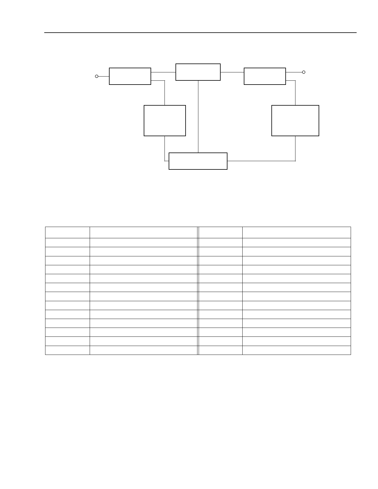
Block Diagram
OPTICAL
INPUT
SIGNAL
INPUT TAP
OPTICAL GAIN
PD #1
INPUT POWER
MONITOR
Data Sheet, Rev. 1
September 2001
OUTPUT TAP
OPTICAL
OUTPUT
SIGNAL
PD #2
OUTPUT POWER
MONITOR
MICROCONTROLLER
Figure 1. W1724-Type EDFA Block Diagram
1-904 (C)
Pin Information
Table 1. Pin Descriptions for a Microcontrolled (Full) Amplifier
Pin
Description
Pin
Description
1
5.0 V (±0.25 V)
2
5.0 V (±0.25 V)
3
5.0 V (±0.25 V)
4
5.0 V (±0.25 V)
5
Reserved1
6
Reserved1
7
EDFA Temperature Alarm
8
Loss of Output Power Alarm2
9
Pumps Bias Alarm3
10
Pumps Temperature Alarm4
11
EDFA Shutdown Override5
12
5.0 V (±0.25 V)
13
GND
14
GND
15
GND
16
GND
17
GND
18
RS-232 OUT (TTL)
19
Loss of Input Power Alarm6
20
Reserved1
21
Amplifier Disable Input7
22
RS-232 IN (TTL)
23
Reserved1
24
5.0 V (±0.25 V)
25
GND
—
—
1. Do not connect to reserved pins.
2. Normal = TTL low, alarm = TTL high if the output power falls 2 dB below the minimum value.
3. Normal = TTL low, alarm = TTL high if pump bias exceeds 95% of its end-of-life value.
4. Normal = TTL low, alarm = TTL high if pump temperature exceeds 35 °C.
5. The EDFA is equipped with an optical transient suppression feature when this pin is tied to GND. The EDFA will turn all pumps off, if the
input power is too low. Tying this pin to 5 V will disable this feature; however, damage to the optical connectors and components may occur if
the amplifier is turned on without the presence of an optical signal.
6. Normal = TTL low, alarm = TTL high if input power is less than 2 dB below minimum PIN.
7. Amplifier enable (all pumps are on) = TTL low, amplifier disable (all pumps are off) = TTL high.
Agere Systems Inc.
3
Share Link: