P80C550 查看數據表(PDF) - Philips Electronics
零件编号
产品描述 (功能)
比赛名单
P80C550
Philips Electronics

P80C550 Datasheet PDF : 28 Pages
| |||
Philips Semiconductors
80C51 8-bit microcontroller family
4K/128 OTP/ROM/ROMless, 8 channel 8 bit A/D, watchdog timer
Product specification
80C550/83C550/87C550
Sample A/D Routines
The following routines demonstrate two methods of operating the
A/D converter. The first method uses polling to determine when the
A/D conversion is complete. The second method uses the A/D
interrupt to flag the end of conversion.
The routine ReadAD will start a read of the A/D channel identified by
R7, and wait for the conversion to complete, polling the A/D interrupt
flag. The result is returned in the accumulator.
ReadAD:MOV A,#08h
;Basic A/D start command.
ORL A,R7
;Add channel # to be read.
MOV ADCON,A; ;Start A/D.
ADLoop: MOV A,ADCON ;Get A/D status.
JNB ACC.4,ADLoop;Wait for ADCI (A/D ;finished).
MOV A,ADAT
;Get conversion result
MOV ADCON,#0 ;Clear ADCI.
RET
The routine StartAD will start a read of the A/D channel identified by
R7 and exit back to the calling program. When the conversion is
complete, the A/D interrupt occurs, calling the A/D interrupt service
routine. The result of the conversion is returned in register R6.
StartAD: MOV A,#08h
ORL A,R7
MOV ADCON,A
RET
.
.
.
ORG 2Bh
ADInt: MOV R6,ADAT
MOV ADCON,#0
RETI
;Basic A/D start command.
;Add channel # to be read.
;Start A/D.
;A/D interrupt address.
;Get conversion result.
;Clear ADCI.
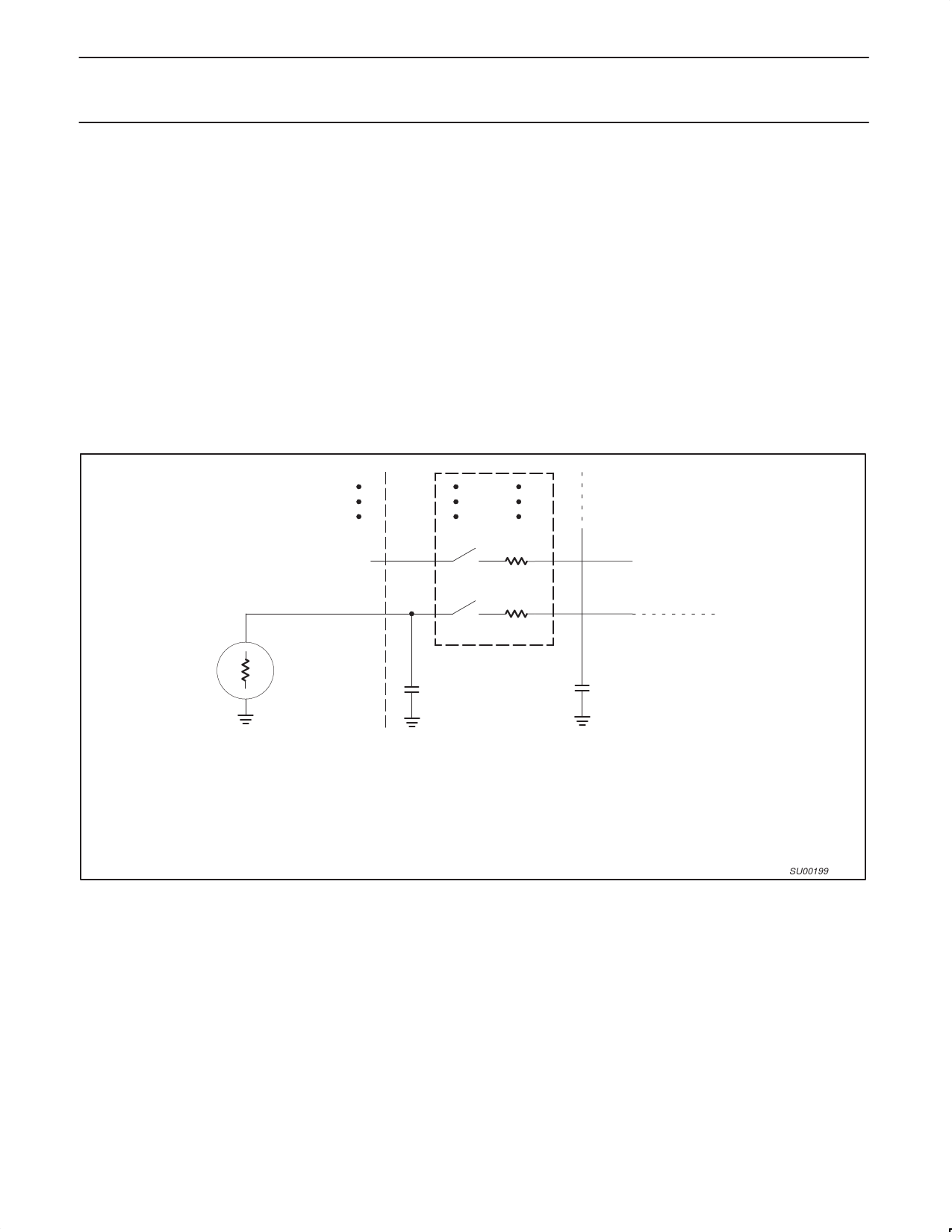
IN+1
SmN+1 RmN+1
SmN
RmN
IN
To Comparator
+
Multiplexer
RS
VANALOG
CS
CC
INPUT
Rm = 0.5 - 3 kΩ
CS + CC = 15pF maximum
RS = Recommended < 9.6 kΩ for 1 LSB @ 12MHz
NOTE:
Because the analog to digital converter has a sampled-data comparator, the input looks capacitive to a source. When a conversion
is initiated, switch Sm closes for 8tcy (8µs @ 12MHz crystal frequency) during which time capacitance Cs + Cc is charged. It should
be noted that the sampling causes the analog input to present a varying load to an analog source.
Figure 3. A/D Input: Equivalent Circuit
SU00199
1998 May 01
9
Share Link: