AIC1783 查看數據表(PDF) - Analog Intergrations
零件编号
产品描述 (功能)
比赛名单
AIC1783 Datasheet PDF : 11 Pages
| |||
AIC1783
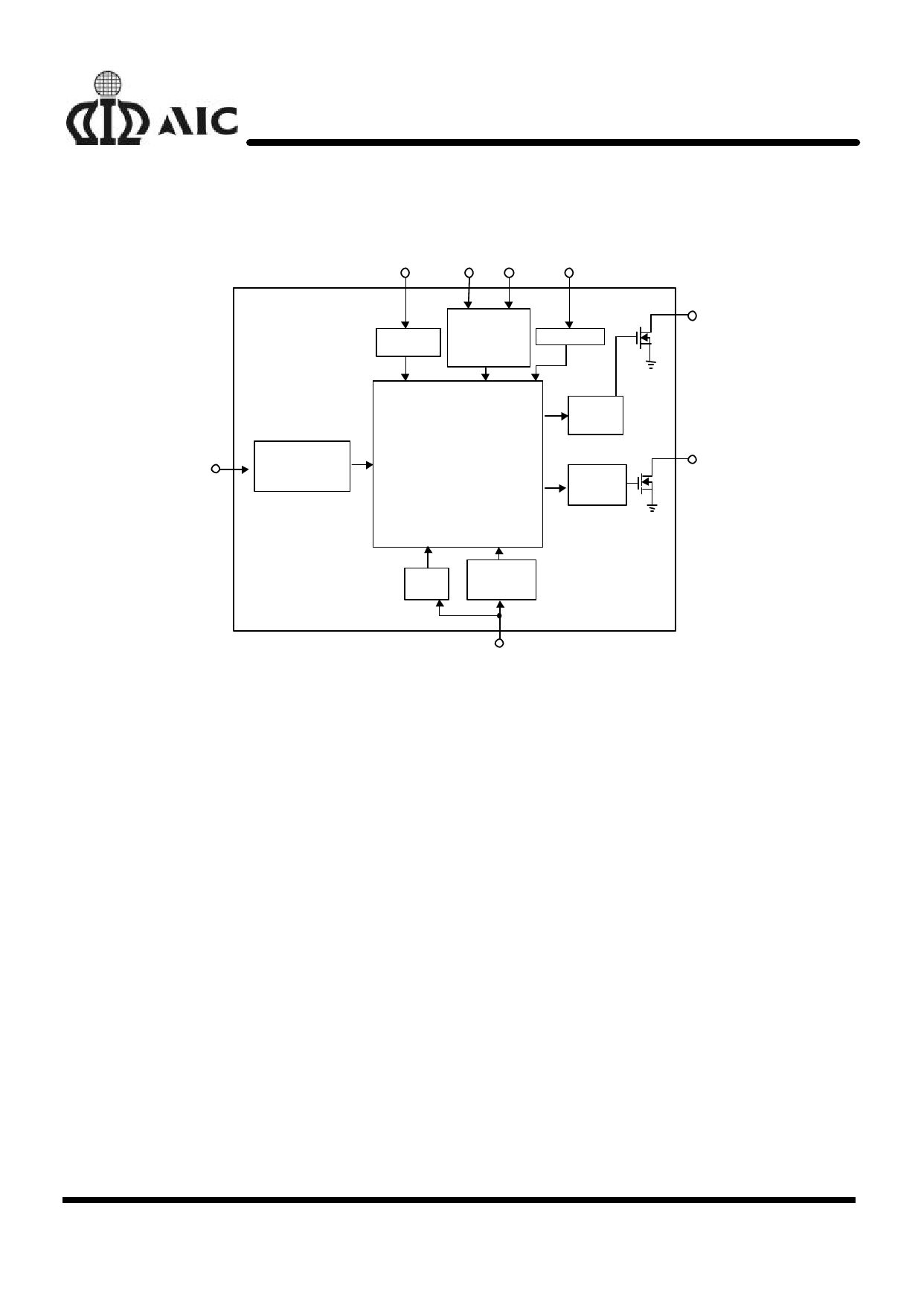
n BLOCK DIAGRAM
MODE
GND VCC
TIMER
REF
Battery Voltage
Protection Setting
MODE
Selection
Bandgap
Reference &
Voltage
Regulator
Oscillator
Charge Control
State Machine
Display
Control
Unit
Charge
Control Unit
LED
ICON
13-bit
A/D
Battery
Voltage
Protection
n PIN DESCRIPTIONS
PIN 1: REF- Reference voltage input,
acceptable voltage range :
(VCC-1.4V) ~ (0.5VCC-0.4V)
PIN 2: TIMER- Determining the period of
safety timer with an external
resistor connected to GND.
PIN 3: MODE- Determining the mode of
operation for the AIC1783.
PIN 4: GND- Power ground.
VBT
PIN 5: LED- Open-drained output used to
indicate the battery charging
status.
PIN 6: ICON- Open-drained output, used to
control the charging current to
the battery.
PIN 7: VBT- Divided battery voltage input to
sense the battery voltage.
PIN 8: VCC- Power supply input at 5V±10%.
6
Share Link: 