AN201 查看數據表(PDF) - Vishay Semiconductors
零件编号
产品描述 (功能)
比赛名单
AN201 Datasheet PDF : 11 Pages
| |||
AN201
Vishay Siliconix
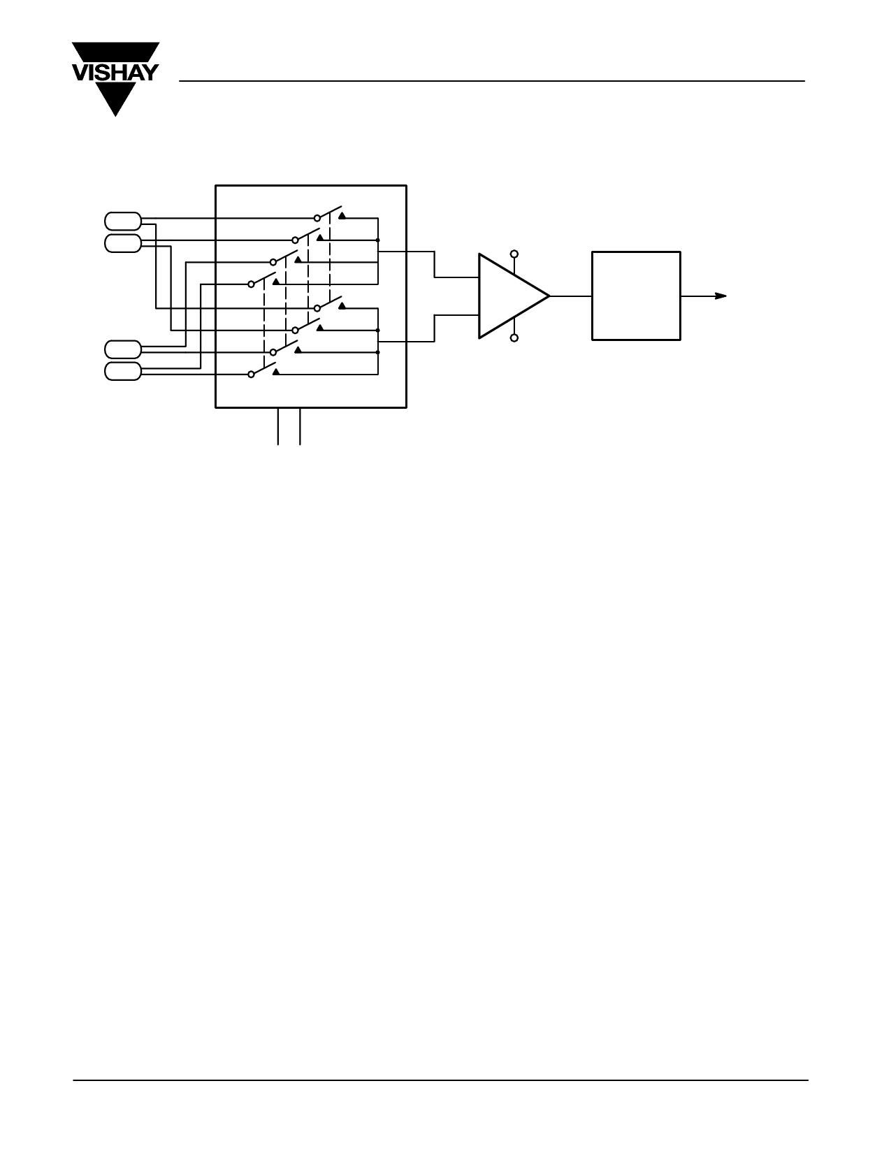
TC1
Instrumentation
TC2
Amplifier
+15 V
+
AV = 100
–
A/D
Converter
Output
–15 V
TC3
TC4
DG409
A0 A1
FIGURE 13. Differential Multiplexing of Thermocouples
The advantages of low-level or high-level transmission is
again dictated by system configuration and cost.
Preamplification at the transducer will provide low source
impedance and voltage gain, but it introduces the problem of
supplying power to the amplifier.
The transmission cable carrying the transducer signal is
critical in a low-level system; it should be as short as practical.
Signal conductors should be tightly twisted for minimum
enclosed area. This technique guards against picking up
electromagnetic interference and shields the twisted pair of
wires against capacitively-coupled (electrostatic)
interference. A key requirement for the transmission cable is
that it presents a balanced line to the source of noise
interference. This requires an equal series impedance in each
conductor and an equally distributed impedance from each
conductor to ground. The result should be that noise will be
coupled in phase to both conductors and rejected as
common-mode voltages. Coaxial cable is not suitable for
low-level signals because the two conductors (center and
shield) are unbalanced. Also ground loops are produced if the
shield is grounded at both ends by standard baby “N”
connector sockets. If coaxial cable is used, the signal should
be carried on the center conductors of two equal-length cables
whose shield is terminated only at the transducer end.
Document Number: 70600
05-Aug -99
Silicon in contact with aluminum creates a thermocouple
voltage. In a typical multiplexer, the source voltage will be
exactly canceled by the drain voltage, but large thermal
gradients between source and drain contacts can produce a
net offset voltage. The low current consumption of the DG409
("75 mA) translates into minimal errors due to thermocouple
offsets.
Programmable Amplifier
Figure 14 shows a programmable amplifier with selectable
inputs. This configuration is used in auto-ranging digital volt
meters, signal conditioners, etc. Its purpose is to select
optimum gain ready for conversion.
Gain ratios are a function of the resistor ratios. Sources of error
will be due to the on-resistance of the switches contributing to
the resistor ratio. The low on-resistance of the DG408
(typically 40 W at 25_C) and close matching should minimize
ranging errors introduced by the switches. The switching
speed of the DG408 will allow the preferred value of gain to be
attained quickly.
www.vishay.com
9
Share Link: 