APN1001 查看數據表(PDF) - Skyworks Solutions
零件编号
产品描述 (功能)
比赛名单
APN1001 Datasheet PDF : 5 Pages
| |||
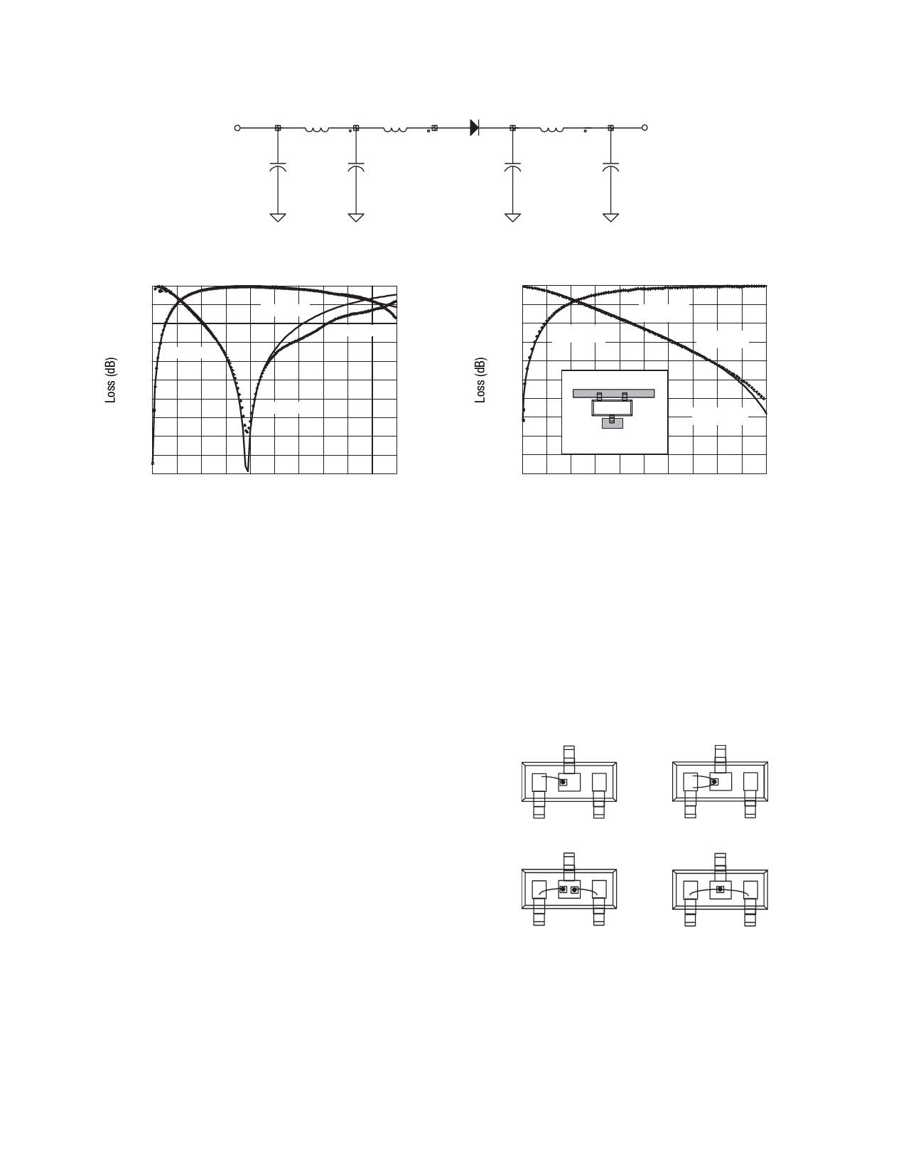
APPLICATION NOTE • APN1001: CIRCUIT MODELS FOR PLASTIC PACKAGED MICROWAVE DIODES
L = 0.57 nH
L = 0.05 nH
C = 0.2 pF
C = 0.02 pF
L = 0.57 nH
C = 0.02 pF
C = 0.2 pF
Figure 3. SOD-323 Circuit Model
0
Isolation
-20
Simulated
Measured
Return Loss
-40
0.1
10.0
Frequency (GHz)
Figure 4. Measurement vs. Model Simulation
of a SOT-23 Package
0
Isolation
Return Loss
Simulated
-20
-40
0.1
Center Conductor
Ground
Measured
10.0
Frequency (GHz)
Figure 5. SOT-23 Validation:
Simulation vs. Measurement
Impedance Measurements
The HP 4291A Impedance Analyzer, an instrument based on mea-
suring the vector V/I with coverage from 1 MHz–1.8 GHz, was
also utilized to characterize inductance of the packages under
consideration. Measurements were taken on a group of PIN
diodes that were forward biased to low values of forward resis-
tance. The inductance values derived from these measurements
are shown in Table 1 and compare well with the values derived
from network analysis. The advantage of the direct impedance
measurement is the capability of a quick measurement without
the necessity of hard bonding the device to a substrate.
Alternative SOT-23 Designs for
Lower Inductance
To reduce the total inductance of the SOT-23 package, alternative
wire bonding schemes were studied. Figure 6 shows four
bonding wire designs considered in this study. The measured
inductance of these bonding schemes are shown on Table 1.
Validation of Simulated Model
Validation of the model was performed by placing the diode into a
test circuit that simulates a shunt connected switch. The test cir-
cuit was constructed using a Duriod microstrip board and the
device was placed as shown in Figure 5. This provided a different
operating environment because not only was the diode connected
differently, but the microstrip insulator had a different dielectric
constant.
The measured performance of this circuit was imported into the
circuit simulator and compared to a simulation using the circuit
model. Figure 6 shows good validation of the network analyzer
generated model.
Single
Parallel Wires
Common Cathode
Dual Contact
Figure 6. SOT-23 Configurations
Skyworks Solutions, Inc. • Phone [781] 376-3000 • Fax [781] 376-3100 • sales@skyworksinc.com • www.skyworksinc.com
2
July 21, 2005 • Skyworks Proprietary Information • Products and Product Information are Subject to Change Without Notice. • 200311 Rev. A
Share Link: 