BA3423S 查看數據表(PDF) - ROHM Semiconductor
零件编号
产品描述 (功能)
比赛名单
BA3423S Datasheet PDF : 18 Pages
| |||
Audio ICs
BA3423S
(6) ALC amplifier
The *30dBm standard level signal mixed by the mixing
resistor enters a *17dB attenuator before the ALC am-
plifier. This attenuator resistance and an electronic vol-
ume are used by the ALC. The ALC amplifier standard
input level is *47dBm, and its gain is 40dB, giving a
standard output level of *7dBm. The standard output
level of the ALC amplifier is compared to the ALC level
(*3.7dBm), and if signals above this level are input the
ALC operates. The attack and recovery times are deter-
mined by the CR circuit connected to the T pin (pin 9).
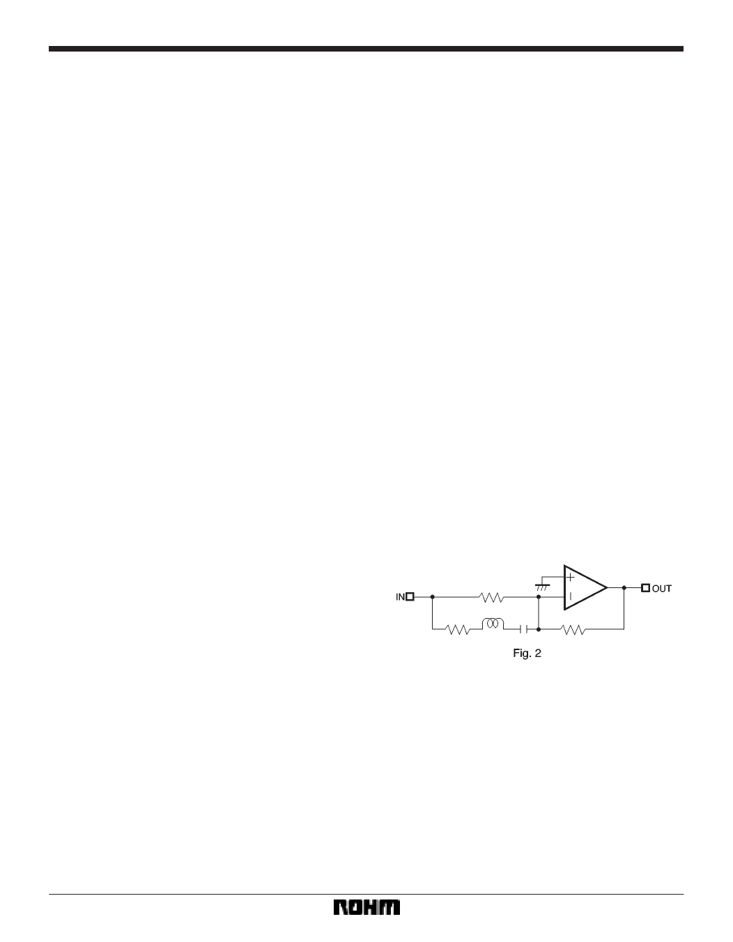
(7) Recording equalizer amplifier
The standard signal level is *7dBm (from the ALC am-
plifier output), and has treble peaking characteristic at-
tributed to it by the recording equalizer amplifier. The ex-
ternal capacitors connected between pins 5, 6 and 7, and
pins 10, 11 and 12 form an equivalent inductor circuit, and
the series impedance of this LCR circuit connected in
parallel with the on-chip resister form the input imped-
ance of the inverting amplifier and give it its peaking char-
acteristic. The equivalent circuit is shown in Fig. 1. If the
Nor / HS pin (pin 21) is driven HIGH, the values of the two
resisters change, to give the peaking characteristic for
high-speed dubbing. In the past, the recording current
peaking characteristic was formed by switching the cir-
cuit constant values of a fixed-current CR circuit. With the
BA3423AS, this is incorporated on the chip. The gain of
this stage is 0dB at 1kHz, and the recording output stan-
dard level is *7dBm. As the maximum output voltage of
the recording output pin (Tape B pins 3 and 4) is 4.5dBm
(at VCC = 5.5V), for sudden, large inputs, even during the
attack time period until the ALC starts operating, the dy-
namic range is 4.5dBm - the recording output standard
level (*7dBm), i.e. –11.5dBm. This allows low-distortion
recording. The frequency response of the recording cur-
rent flowing through the head is shown in Figs. 17 to 19.
This is the response characteristic for fixed input voltage
to the Aux In pins (pins 24 and 25). The factors that deter-
mine the recording current characteristics are the peak-
ing characteristics of the peaking circuit, and the external
fixed-current circuit. The value of the fixed-current circuit
resistor (Ro) is calculated using the following formula.
The recording output standard level is *7dBm, f = 1kHz,
and the standard recording current required is 37µA
(rms).
*7dBm / (RH + RO) = 37µArms
RH: DC resistance at the head
If RH is 500Ω, Ro is approximately 8.2kΩ. The basic val-
ues for the capacitors for the external constant-current
circuit and recording equalizer amplifier are:
C0 = 820pF
CL1 (between pins 6 and 7, and pins 11
and 12) = 2700pF
CL2 (between pins 5 and 6, and pins 10
and 11) = 470pF
Characteristic curves for different values of C0, CL1 and
CL2 are given in Figs. 17, 18 and 19 respectively. Select
the values for these components after considering the
characteristics of the head to be used, and the overall re-
cording and playback frequency characteristics.
(8) Recording output switch
The Tape B pins (pins 3 and 4) are used as both the B
mechanism input pins, and recording output pins, and
the recording output switch is used to switch between
them. When the input to the Rec / PB pin (pin 19) is “H”,
recording output is selected, and when it is open, Tape
B input is selected. This reduces the complexity of the re-
cording head switch circuitry, and requires just two cir-
cuits. Transient muting is used to suppress the “pop”
sound that accompanies switching.
(9) Control pins
The control pin inputs and the corresponding states of
the various inputs and outputs are summarized in the in-
put / output pin status table that follows.
261
Share Link: 