CM1200HC-90R 查看數據表(PDF) - Mitsumi
零件编号
产品描述 (功能)
比赛名单
CM1200HC-90R Datasheet PDF : 8 Pages
| |||
< HVIGBT MODULES >
CM1200HC-90R
HIGH POWER SWITCHING USE
INSULATED TYPE
4th-Version HVIGBT (High Voltage Insulated Gate Bipolar Transistor) Modules
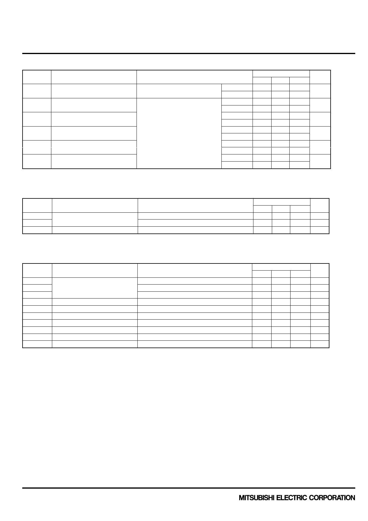
ELECTRICAL CHARACTERISTICS (continuation)
Symbol
Item
Conditions
VEC
Emitter-collector voltage
(Note 2)
IE = 1200 A (Note 4)
VGE = 0 V
trr
Reverse recovery time
(Note 2)
Irr
Qrr
Erec(10%)
Erec
Reverse recovery current
Reverse recovery charge
Reverse recovery energy
Reverse recovery energy
(Note 2)
(Note 2)
(Note 2)
(Note 5)
(Note 2)
(Note 6)
VCC = 2800 V
IC = 1200 A
VGE = ±15 V
RG(on) = 2.7 Ω
Ls = 150 nH
Inductive load
Limits
Min Typ Max
Unit
Tj = 25°C
— 2.50 —
Tj = 125°C — 2.80 3.40
V
Tj = 25°C
— 0.70 —
Tj = 125°C
—
0.90
—
µs
Tj = 25°C
— 1100 —
Tj = 125°C — 1200 —
A
Tj = 25°C
— 1000 —
Tj = 125°C — 1500 —
µC
Tj = 25°C
— 1.30 —
Tj = 125°C
—
2.10
—
J
Tj = 25°C
— 1.55 —
Tj = 125°C
—
2.40
—
J
THERMAL CHARACTERISTICS
Symbol
Item
Rth(j-c)Q
Rth(j-c)D
Rth(c-s)
Thermal resistance
Contact thermal resistance
Conditions
Limits
Min Typ Max
Unit
Junction to Case, IGBT part
―
― 10.0 K/kW
Junction to Case, FWDi part
―
· Case to heat sink, grease = 1W/m k, D(c-s) = 100m
―
― 19.0 K/kW
6.0
― K/kW
MECHANICAL CHARACTERISTICS
Symbol
Item
Mt
Ms
Mt
m
CTI
da
ds
LP CE
RCC’+EE’
rg
Mounting torque
Mass
Comparative tracking index
Clearance
Creepage distance
Parasitic stray inductance
Internal lead resistance
Internal gate resistance
Conditions
M8 : Main terminals screw
M6 : Mounting screw
M4 : Auxiliary terminals screw
TC = 25°C
TC = 25°C
Note1. Pulse width and repetition rate should be such that junction temperature (Tj) does not exceed Topmax rating.
2. The symbols represent characteristics of the anti-parallel, emitter to collector free-wheel diode (FWDi).
3. Junction temperature (Tj) should not exceed Tjmax rating (150°C).
4. Pulse width and repetition rate should be such as to cause negligible temperature rise.
5. Eon(10%) / Eoff(10%) / Erec(10%) are the integral of 0.1VCE x 0.1IC x dt.
6. Definition of all items is according to IEC 60747, unless otherwise specified.
Limits
Min Typ Max
Unit
7.0
―
22.0 N·m
3.0
―
6.0 N·m
1.0
―
3.0 N·m
―
1.2
―
kg
600
―
―
―
19.5 ―
―
mm
32.0 ―
―
mm
―
11.0
―
nH
― 0.12
―
mΩ
―
1.7
―
Ω
December 2012 HVM-1057-E
3
Share Link: 