EL1881 查看數據表(PDF) - Intersil
零件编号
产品描述 (功能)
比赛名单
EL1881 Datasheet PDF : 11 Pages
| |||
EL1881C
Vertical Sync
A low-going Vertical Sync pulse is output during the start of
the vertical cycle of the incoming video signal. The vertical
cycle starts with a pre-equalizing phase of pulses with a duty
cycle of about 93%, followed by a vertical serration phase
that has a duty cycle of about 15%. Vertical Sync is clocked
out of the EL1881 on the first rising edge during the vertical
serration phase. In the absence of vertical serration pulses,
a vertical sync pulse will be forced out after the vertical sync
default delay time, approximately 60µS after the last falling
edge of the vertical equalizing phase for RSET = 681kΩ.
Odd/Even
Because a typical television picture is composed of two
interlaced fields, there is an odd field that includes all the
odd lines, and an even field that consists of the even lines.
This odd/even field information is decoded by the EL1881
during the end of picture information and the beginning of
vertical information. The odd/even circuit includes a T-flip-
flop that is reset during full horizontal lines, but not during
half lines or vertical equalization pulses. The T-flip-flop is
clocked during each falling edge of these half hperiod
pulses. Even fields will toggle until a low state is clocked to
the odd/even pin 7 at the beginning of vertical sync, and odd
fields will cause a high state to be clocked to the odd/even
pin at the start of the next vertical sync pulse. Odd/even can
be ignored if using non-interlaced video, as there is no
change in timing from one field to the next.
RSET
An external RSET resistor, connected from RSET pin 6 to
ground, produces a reference current that is used internally
as the timing reference for vertical sync width, vertical sync
default delay, burst gate delay and burst width. Decreasing
the value of RSET increases the reference current, which in
turn decreases reference times and pulse widths. A higher
frequency video input necessitates a lower RSET value.
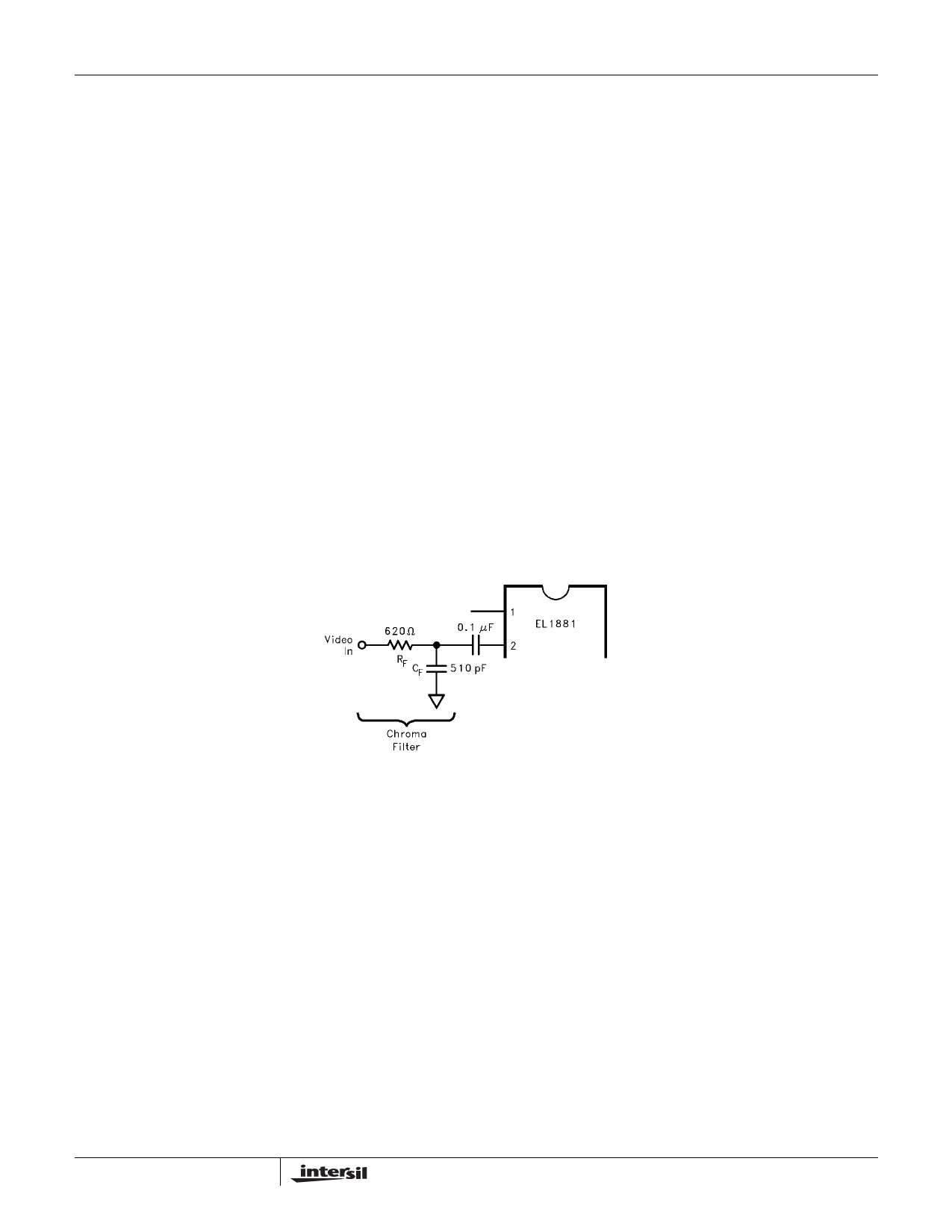
Chroma Filter
A chroma filter is suggested to increase the S/N ratio of the
incoming video signal. Use of the optional chroma filter is
shown in Figure 5. It can be implemented very simply and
inexpensively with a series resistor of 620Ω and a parallel
capacitor of 500pF, which gives a single pole roll-off
frequency of about 500kHz. This sufficiently attenuates the
3.58MHz (NTSC) or 4.43MHz (PAL) color burst signal, yet
passes the approximately 15kHz sync signals without
appreciable attenuation. A chroma filter will increase the
propagation delay from the composite input to the outputs.
FIGURE 5.
10
FN7018.1
Share Link: 