G696H263T1 查看數據表(PDF) - Global Mixed-mode Technology Inc
零件编号
产品描述 (功能)
比赛名单
G696H263T1 Datasheet PDF : 8 Pages
| |||
Global Mixed-mode Technology Inc.
G696/G697
Pin Description
PIN
NAME
FUNCTION
1
RESET
(G696L/G697L)
RESET Output remains low while VCC is below
after VCC rises above the reset threshold.
the
reset
threshold,
and
for
delay
time
set
by
CD
RESET (G696H)
RESET Output remains high while VCC is below the reset threshold, and for delay time set by CD
after VCC rises above the reset threshold.
2
VCC
Supply Voltage (+5V, +3.3V, +3.0V)
3
GND
Ground
4
N.C.
No Connection.
5
CD
External Programmable time delay is set by the capacitor connect to CD pin.
Detailed Description
A microprocessor’s (µP’s) reset input starts the µP in a
known state. The G697L/G696L/G696H assert reset to
prevent code-execution errors during power-up,
power-down, or brownout conditions. They assert a
reset signal whenever the VCC supply voltage declines
below a preset threshold (VTH-), keeping it asserted for
time delay set by capacitor connected to CD pin, after
VCC has risen above the high reset threshold VTH+
(VTH-+VHYS). The G697L uses an open-drain output,
and the G696L/G696H have a push-pull output stage.
Connect a pull-up resistor on the G697L’s RESET out-
put to any supply between 0 and 5.5V.
must be valid down to 0V, adding a pull-down resistor
to RESET causes any stray leakage currents to flow
to ground, holding RESET low (Figure 4). R1’s value
is not critical; 100kΩ is large enough not to load
RESET and small enough to pull RESET to ground.
A 100kΩ pull-up resistor to VCC is also recommended
for the G697L if RESET is required to remain valid
for VCC < 0.8V.
VCC
The time delay is set by external capacitor CD, and
internal pull up resistor RD. When the voltage at CD
pin exceeds the buffer threshold, typically 0.675 VCC,
the RESET output high (RESET output low). The
voltage detector and buffer have built-in hysterisis to
prevent erratic reset operation. The formula of time
delay is T (ms) ≅ 1685 CD (µF). Fig1 and Fig2 show a
timing deagram and a Functional Block.
VCC
G697
RESET
GND
RPULL-UP
VCC
µP
RESET MOTOROLA
INPUT 68HCXX
GND
VCC
G696
RESET
GND
R1
100k
Figure3. RESET Valid to VCC = Ground Circuit
Ensuring a Valid Reset Output Down to VCC = 0
When VCC falls below 0.8V, the G696 RESET output
no longer sinks current—it becomes an open circuit.
Therefore, high-impedance CMOS logic inputs con-
nected to RESET can drift to undetermined voltages.
This presents no problem in most applications since
most µP and other circuitry is inoperative with VCC
below 0.8V. However, in applications where RESET
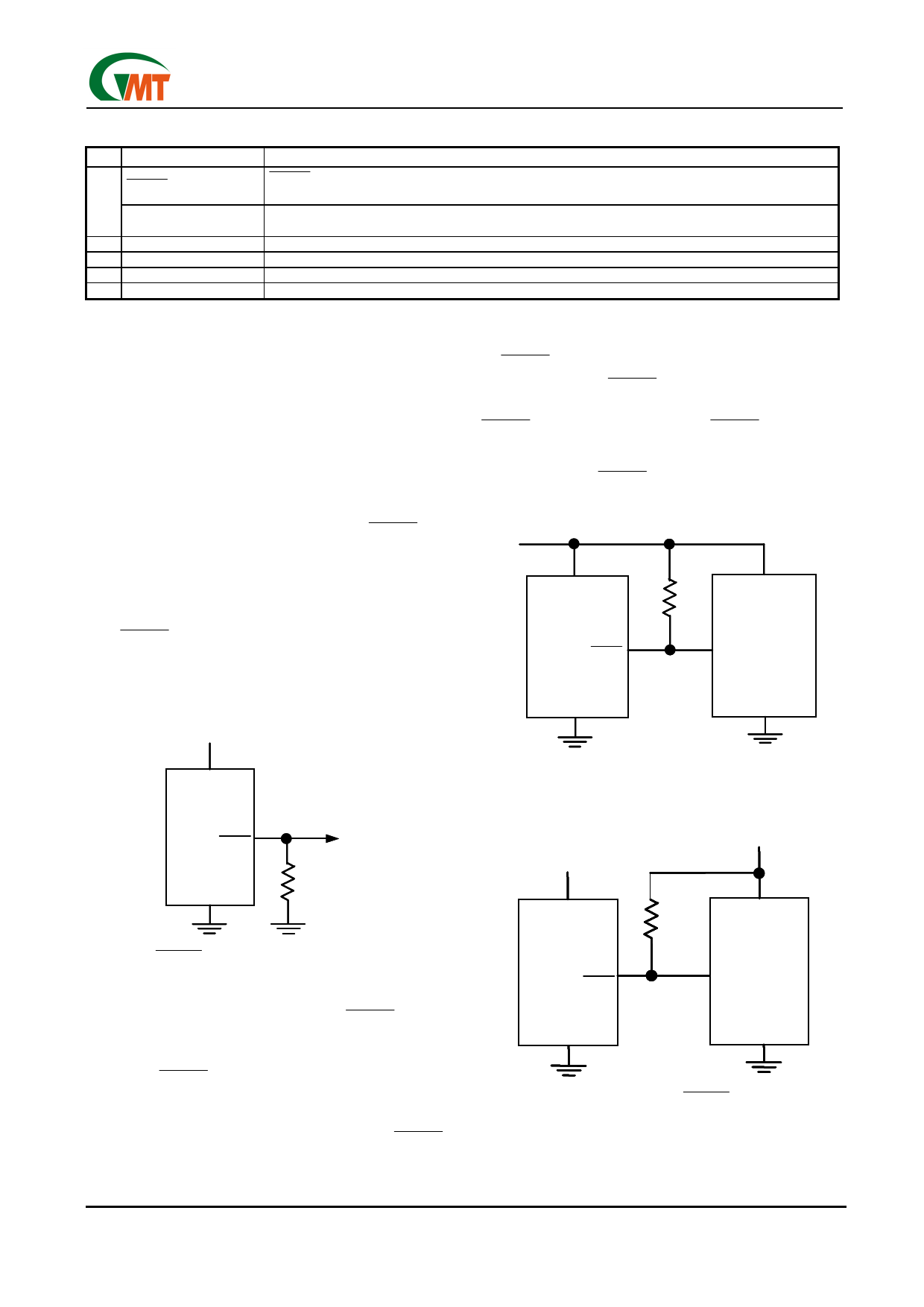
Figure 4. Interfacing to µPs with Bidirectional Reset
I/O
+3.3V
VCC
G697
RESET
+5.0V
RPULL-UP
VCC
5V SYSTEM
RESET
INPUT
GND
GND
Figure 5. G697L Open-Drain RESET Output Allows
Use with Multiple Supplies
Ver: 1.1
Jul 26, 2002
TEL: 886-3-5788833
http://www.gmt.com.tw
6
Share Link: 