ISL8487(2003) 查看數據表(PDF) - Intersil
零件编号
产品描述 (功能)
比赛名单
ISL8487
(Rev.:2003)
(Rev.:2003)
Intersil

ISL8487 Datasheet PDF : 13 Pages
| |||
ISL8487, ISL81483, ISL81487
Twisted pair is the cable of choice for RS-485/RS-422
networks. Twisted pair cables tend to pick up noise and
other electromagnetically induced voltages as common
mode signals, which are effectively rejected by the
differential receivers in these ICs.
To minimize reflections, proper termination is imperative
when using the 5Mbps device. Short networks using the
250kbps versions need not be terminated, but, terminations
are recommended unless power dissipation is an overriding
concern.
In point-to-point, or point-to-multipoint (single driver on bus)
networks, the main cable should be terminated in its
characteristic impedance (typically 120Ω) at the end farthest
from the driver. In multi-receiver applications, stubs
connecting receivers to the main cable should be kept as
short as possible. Multipoint (multi-driver) systems require
that the main cable be terminated in its characteristic
impedance at both ends. Stubs connecting a transceiver to
the main cable should be kept as short as possible.
Built-In Driver Overload Protection
As stated previously, the RS-485 spec requires that drivers
survive worst case bus contentions undamaged. These
devices meet this requirement via driver output short circuit
current limits, and on-chip thermal shutdown circuitry.
The driver output stages incorporate short circuit current
limiting circuitry which ensures that the output current never
exceeds the RS-485 spec, even at the common mode
voltage range extremes. Additionally, these devices utilize a
foldback circuit which reduces the short circuit current, and
thus the power dissipation, whenever the contending voltage
exceeds either supply.
In the event of a major short circuit condition, these devices
also include a thermal shutdown feature that disables the
drivers whenever the die temperature becomes excessive.
This eliminates the power dissipation, allowing the die to
cool. The drivers automatically re-enable after the die
temperature drops about 15 degrees. If the contention
persists, the thermal shutdown/re-enable cycle repeats until
the fault is cleared. Receivers stay operational during
thermal shutdown.
Low Power Shutdown Mode (Excluding ISL81487)
These CMOS transceivers all use a fraction of the power
required by their bipolar counterparts, but the ISL8487 and
ISL81483 include a shutdown feature that reduces the
already low quiescent ICC to a 1nA trickle. They enter
shutdown whenever the receiver and driver are
simultaneously disabled (RE = VCC and DE = GND) for a
period of at least 600ns. Disabling both the driver and the
receiver for less than 50ns guarantees that shutdown is not
entered.
Note that receiver and driver enable times increase when
enabling from shutdown. Refer to Notes 5-9, at the end of
the Electrical Specification table, for more information.
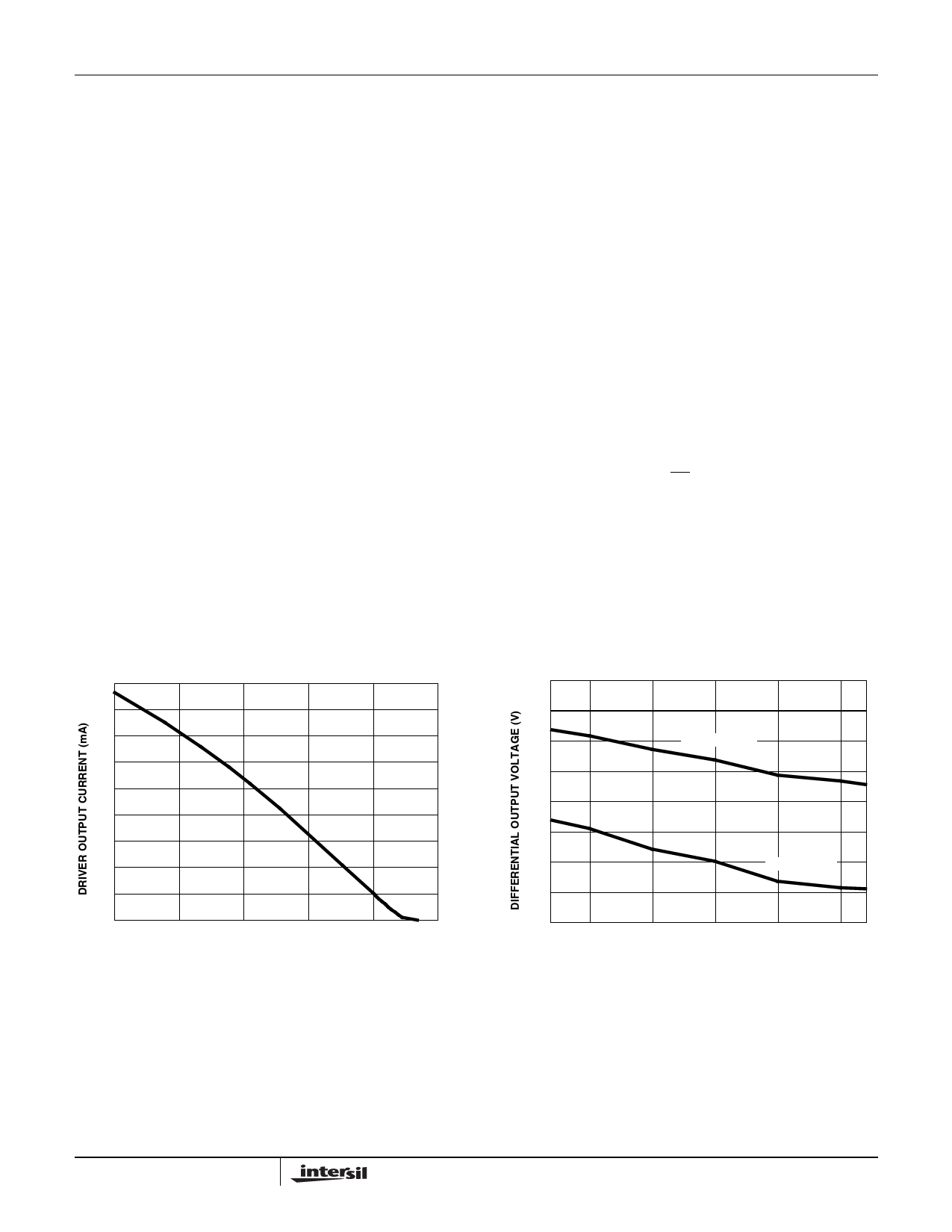
Typical Performance Curves VCC = 5V, TA = 25oC, ISL8487, ISL81483 and ISL81487; Unless Otherwise Specified
90
3.6
80
3.4
70
3.2
RDIFF = 100Ω
60
3
50
2.8
40
2.6
30
20
2.4
RDIFF = 54Ω
10
2.2
0
0
1
2
3
4
5
DIFFERENTIAL OUTPUT VOLTAGE (V)
FIGURE 6. DRIVER OUTPUT CURRENT vs DIFFERENTIAL
OUTPUT VOLTAGE
2
-40 -25
0
25
50
75 85
TEMPERATURE (oC)
FIGURE 7. DRIVER DIFFERENTIAL OUTPUT VOLTAGE vs
TEMPERATURE
9
Share Link: