AIC1570 查看數據表(PDF) - Analog Intergrations
零件编号
产品描述 (功能)
比赛名单
AIC1570
Analog Intergrations

AIC1570 Datasheet PDF : 18 Pages
| |||
AIC1570
LUV
OC1
0.2V
SS
3.6V
OV
OVER CURRENT
LATCH
S
Q
INHIBIT
R
+
S
COUNTER
R
FAULT LATCH
S
VCC
+
POR
RQ
FAULT
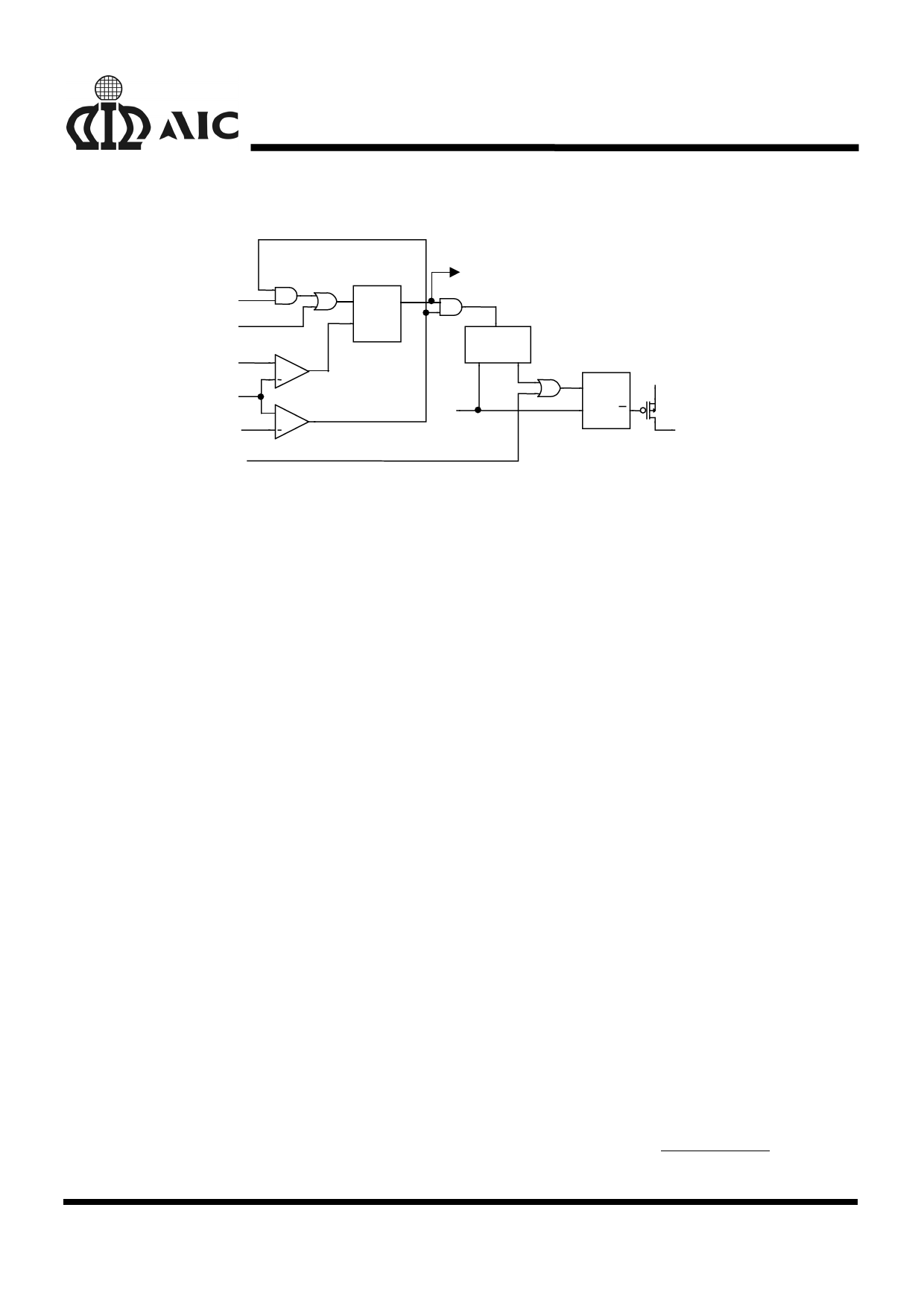
Fig. 10 Simplified Schematic of Fault Logic
A simplified schematic is shown in figure 10. An
over-voltage detected on VSEN immediately sets
the fault latch. A sequence of three over-current
fault signals also sets the fault latch. An under-
voltage event on either linear output (FB2 or FB3)
is ignored until the soft-start interval. Cycling the
bias input voltage (+12V) off then on reset the
counter and the fault latch.
Over-Voltage Protection
During operation, a short on the upper PWM
MOSFET (Q1) causes VOUT1 to increase. When
the output exceed the over-voltage threshold of
115% of DACOUT, the FAULT pin is set to fault
latch and turns Q2 on as required in order to
regulate VOUT1 to 115% of DACOUT. The fault
latch raises the FAULT pin close to VCC
potential.
A separate over-voltage circuit provides
protection during the initial application of power.
For voltage on VCC pin below the power-on reset
(and above 4V), should VSEN exceed 0.7V, the
lower MOSFET (Q2) is driven on as needed to
regulate VOUT1 to 0.7V.
Over-Current Protection
All outputs are protected against excessive over-
current. The PWM controller uses upper
MOSFET’s on-resistance, RDS(ON) to monitor the
current for protection against shorted outputs.
The linear regulator monitors the current limit in
excess of 500mA. Additionally, both the linear
regulator and controller monitor FB2 and FB3 for
under-voltage to protect against excessive
current.
When the voltage across Q1 (ID•RDS(ON)) exceeds
the level (200µA•ROCSET), this signal inhibit all
outputs. Discharge soft-start capacitor (Css) with
10µA current sink, and increments the counter.
Css recharges and initiates a soft-start cycle
again until the counter increments to 3. This sets
the fault latch to disable all outputs. Fig. 6
illustrates the over-current protection until an
over load on OUT1.
Should excessive current cause FB2 or FB3 to
fall below the linear under-voltage threshold, the
LUV signal sets the over-current latch if Css is
fully charged. Cycling the bias input power off
then on reset the counter and the fault latch.
The over-current function for PWM controller will
trip at a peak inductor current (IPEAK) determined
by:
IPEAK
=
IOCSET × ROCSET
RDS(ON)
11
Share Link: