LT3023 查看數據表(PDF) - Linear Technology
零件编号
产品描述 (功能)
比赛名单
LT3023 Datasheet PDF : 16 Pages
| |||
LT3023
APPLICATIONS INFORMATION
Output Capacitance and Transient Response
The LT3023 regulator is designed to be stable with a
wide range of output capacitors. The ESR of the out-
put capacitor affects stability, most notably with small
capacitors. A minimum output capacitor of 1μF with an
ESR of 3Ω or less is recommended to prevent oscilla-
tions. The LT3023 is a micropower device and output
transient response will be a function of output capacitance.
Larger values of output capacitance decrease the peak
deviations and provide improved transient response for
larger load current changes. Bypass capacitors, used to
decouple individual components powered by the LT3023,
will increase the effective output capacitor value. With
larger capacitors used to bypass the reference (for low
noise operation), larger values of output capacitors are
needed. For 100pF of bypass capacitance, 2.2μF of output
capacitor is recommended. With a 330pF bypass capacitor
or larger, a 3.3μF output capacitor is recommended. The
shaded region of Figure 2 defines the region over which
the LT3023 regulator is stable. The minimum ESR needed
is defined by the amount of bypass capacitance used, while
the maximum ESR is 3Ω.
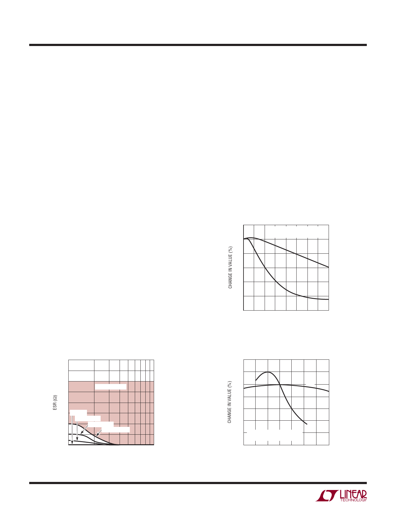
Extra consideration must be given to the use of ceramic
capacitors. Ceramic capacitors are manufactured with a
variety of dielectrics, each with different behavior across
temperature and applied voltage. The most common
dielectrics used are specified with EIA temperature char-
acteristic codes of Z5U, Y5V, X5R and X7R. The Z5U and
Y5V dielectrics are good for providing high capacitances
in a small package, but they tend to have strong voltage
and temperature coefficients as shown in Figures 3 and 4.
When used with a 5V regulator, a 16V 10μF Y5V capacitor
can exhibit an effective value as low as 1μF to 2μF for the
DC bias voltage applied and over the operating tempera-
ture range. The X5R and X7R dielectrics result in more
stable characteristics and are more suitable for use as the
output capacitor. The X7R type has better stability across
temperature, while the X5R is less expensive and is avail-
able in higher values. Care still must be exercised when
using X5R and X7R capacitors; the X5R and X7R codes
only specify operating temperature range and maximum
capacitance change over temperature. Capacitance change
due to DC bias with X5R and X7R capacitors is better than
Y5V and Z5U capacitors, but can still be significant enough
to drop capacitor values below appropriate levels. Capaci-
tor DC bias characteristics tend to improve as component
20
BOTH CAPACITORS ARE 16V,
1210 CASE SIZE, 10μF
0
X5R
–20
–40
–60
Y5V
–80
–100
0 2 4 6 8 10 12 14 16
DC BIAS VOLTAGE (V)
3023 F03
Figure 3. Ceramic Capacitor DC Bias Characteristics
4.0
3.5
3.0
STABLE REGION
2.5
2.0
1.5 CBYP = 0
CBYP = 100pF
1.0
CBYP = 330pF
CBYP > 3300pF
0.5
0
1
2
3 4 5 6 7 8 9 10
OUTPUT CAPACITANCE (μF)
3023 F02
Figure 2. Stability
10
40
20
0
X5R
–20
–40
Y5V
–60
–80 BOTH CAPACITORS ARE 16V,
1210 CASE SIZE, 10μF
–100
–50 –25 0 25 50 75
TEMPERATURE (°C)
100 125
3023 F04
Figure 4. Ceramic Capacitor Temperature Characteristics
3023fa
Share Link: 