M38C88EA-XXXFP 查看數據表(PDF) - MITSUBISHI ELECTRIC
零件编号
产品描述 (功能)
比赛名单
M38C88EA-XXXFP Datasheet PDF : 51 Pages
| |||
PRELIMINARY NSocothimcaene:gpTeah.riasmisetnrioct laimfiintsalasrepescuibfijceacttioton.
MITSUBISHI MICROCOMPUTERS
38C8 Group
SINGLE-CHIP 8-BIT CMOS MICROCOMPUTER
FUNCTIONAL DESCRIPTION
CENTRAL PROCESSING UNIT (CPU)
The 38C8 group uses the standard 740 family instruction set. Refer
to the table of 740 family addressing modes and machine instruc-
tions or the 740 Family Software Manual for details on the instruction
set.
Machine-resident 740 family instructions are as follows:
The FST and SLW instruction cannot be used.
The STP, WIT, MUL, and DIV instruction can be used.
[Accumulator (A)]
The accumulator is an 8-bit register. Data operations such as data
transfer, etc., are executed mainly through the accumulator.
[Index Register X (X)]
The index register X is an 8-bit register. In the index addressing modes,
the value of the OPERAND is added to the contents of register X and
specifies the real address.
[Index Register Y (Y)]
The index register Y is an 8-bit register. In partial instruction, the
value of the OPERAND is added to the contents of register Y and
specifies the real address.
[Stack Pointer (S)]
The stack pointer is an 8-bit register used during subroutine calls
and interrupts. This register indicates start address of stored area
(stack) for storing registers during subroutine calls and interrupts.
The low-order 8 bits of the stack address are determined by the con-
tents of the stack pointer. The high-order 8 bits of the stack address
are determined by the stack page selection bit. If the stack page
selection bit is “0” , the high-order 8 bits becomes “0016”. If the stack
page selection bit is “1”, the high-order 8 bits becomes “0116”.
The operations of pushing register contents onto the stack and pop-
ping them from the stack are shown in Figure 6.
Store registers other than those described in Figure 6 with program
when the user needs them during interrupts or subroutine calls.
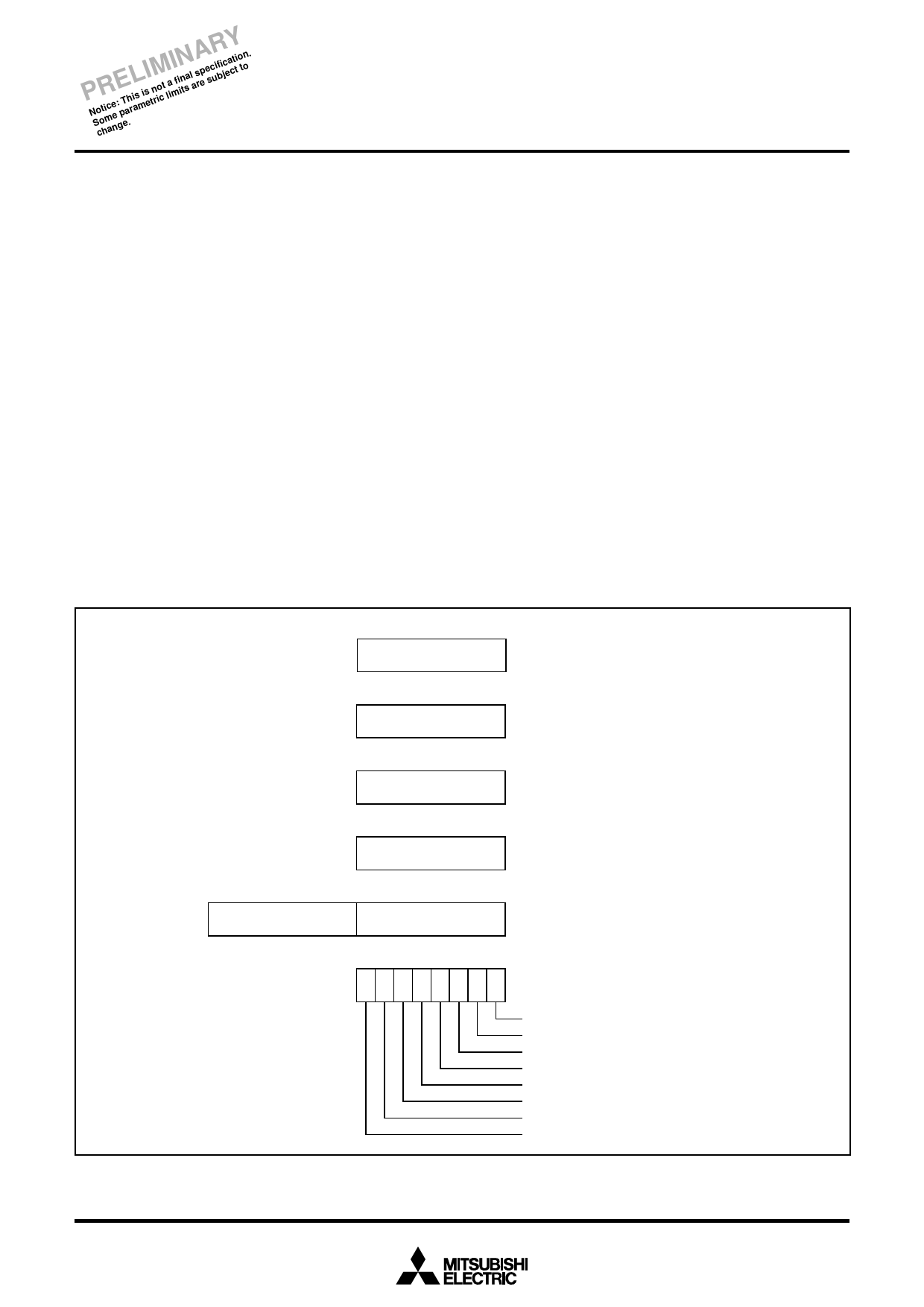
[Program Counter (PC)]
The program counter is a 16-bit counter consisting of two 8-bit regis-
ters PCH and PCL. It is used to indicate the address of the next in-
struction to be executed.
b15
PCH
Fig. 5 740 Family CPU register structure
b7
b0
A
Accumulator
b7
b0
X
Index register X
b7
b0
Y
Index register Y
b7
b0
S
Stack pointer
b7
b0
PCL
Program counter
b7
b0
N V T B D I Z C Processor status register (PS)
Carry flag
Zero flag
Interrupt disable flag
Decimal mode flag
Break flag
Index X mode flag
Overflow flag
Negative flag
7
Share Link: 