MAX608ESA 查看數據表(PDF) - Maxim Integrated
零件编号
产品描述 (功能)
比赛名单
MAX608ESA Datasheet PDF : 12 Pages
| |||
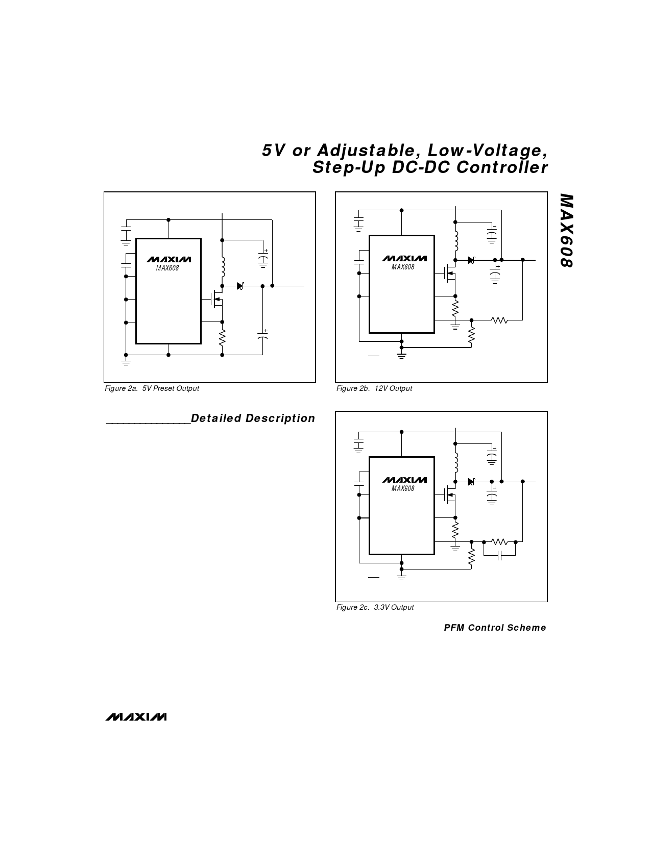
5V or Adjustable, Low-Voltage,
Step-Up DC-DC Controller
VIN = 2V
C3
0.1µF
C2
0.1µF
2
OUT
5 REF
MAX608
4 SHDN
L1
22µH
C1
150µF
D1
1N5817
3 FB
6 AGND
GND
7
1
EXT
8
CS
N
MMFT3055EL
RSENSE
50mΩ
VOUT = 5V
@ 0.5A
C4
200µF
Figure 2a. 5V Preset Output
VIN = 2V
C3
0.1µF
C2
0.1µF
2
OUT
5 REF
4 SHDN MAX608
6 AGND
GND
7
( ) R2 = (R1) VOUT -1
VREF
VREF = 1.5V
L1
22µH
C1
150µF
D1
1N5817
VOUT = 12V
@ 0.3A
1
EXT
8
CS
3
FB
N
MMFT3055EL
C4
200µF
RSENSE
R2
50mΩ
402k
R1
58k
Figure 2b. 12V Output
_______________Detailed Description
The MAX608 is a BiCMOS, step-up, switch-mode pow-
er-supply controller that provides a preset 5V output, in
addition to adjustable-output operation. Its unique con-
trol scheme combines the advantages of pulse-frequen-
cy modulation (low supply current) and pulse-width
modulation (high efficiency with heavy loads), providing
high efficiency over a wide output current range, as well
as increased output current capability over previous
PFM devices. In addition, the external sense resistor
and power transistor allow the user to tailor the output
current capability for each application. Figure 1 shows
the MAX608 functional diagram. The device has a shut-
down mode that reduces the supply current to 5µA
max.
Figure 2 shows the standard application circuits. The
IC is powered from the output, and the input voltage
range is 1.8V to VOUT (this configuration is commonly
known as bootstrap operation). The voltage applied to
the gate of the external power transistor is switched
from VOUT to ground.
The MAX608’s output voltage can be set to 5V by con-
necting FB to ground; it can also be adjusted from 3V
to 16.5V using external resistors. Use 1% external feed-
back resistors when operating in adjustable-output
mode (Figures 2b, 2c) to achieve an overall output volt-
age accuracy of ±5%.
VIN = 2V
C3
0.1µF
C2
0.1µF
2
OUT
5 REF
4 SHDN MAX608
6 AGND
GND
7
( ) R2 = (R1) VOUT -1
VREF
VREF = 1.5V
L1
22µH
C1
150µF
D1
1N5817
1
EXT
8
CS
3
FB
N
SI6426
RSENSE
50mΩ
R1
50k
VOUT = 3.3V
@ 0.6A
C4
200µF
R2
60k
C5
47pF
Figure 2c. 3.3V Output
PFM Control Scheme
The MAX608 uses a proprietary current-limited PFM con-
trol scheme to provide high efficiency over a wide range
of load currents. This control scheme combines the ultra-
low supply current of PFM converters (or pulse skippers)
with the high full-load efficiency of PWM converters.
_______________________________________________________________________________________ 7
Share Link: 