MC74HC377A 查看數據表(PDF) - ON Semiconductor
零件编号
产品描述 (功能)
比赛名单
MC74HC377A Datasheet PDF : 9 Pages
| |||
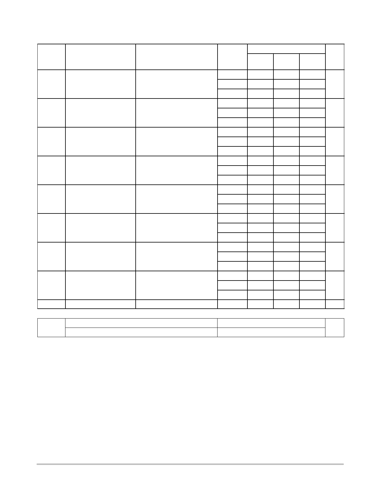
MC74HC377A
AC Electrical Characteristics (CL = 50 pF, Input tr, tf = 6.0 ns)
Symbol
tPHL, tPLH
Parameter
Maximum Propagation Delay
Clock to Qn
Test Conditions
Figures 2, 4
tTHL, tTLH Maximum Output Transition Figures 2, 4
Time
tW
Minimum Clock Pulse Width Figure 2
High or Low
tsu
Minimum Set−up Time
Dn to Clock
tsu
Minimum Set−up Time
Enable to Clock
Figure 3
Figure 3
th
Minimum Hold Time
Dn to Clock
th
Minimum Hold Time
Enable to Clock
Figure 3
Figure 3
fmax
Maximum Clock Pulse
Figures 2, 4
Frequency (50% duty cycle)
Cin
Maximum Input Capacitance
VCC (V)
2.0
4.5
6.0
2.0
4.5
6.0
2.0
4.5
6.0
2.0
4.5
6.0
2.0
4.5
6.0
2.0
4.5
6.0
2.0
4.5
6.0
2.0
4.5
6.0
−
Guaranteed Limits
−555C to
255
≤ 855C ≤ 1255C Unit
160
200
240
ns
32
40
48
27
34
41
75
95
110
ns
15
19
22
13
16
19
80
100
120
ns
16
20
24
4
17
20
60
75
90
ns
12
15
18
10
13
15
60
75
90
ns
12
15
18
10
13
15
3
3
3
ns
3
3
3
3
3
3
4
4
4
ns
4
4
4
4
4
4
6
5
4
ns
30
24
20
35
28
24
10
10
10
pF
CPD
(Note 1)
Power Dissipation Capacitance
Typical @ 255C, VCC = 5.0 V
pF
35
1. CPD is defined as the value of the IC’s equivalent capacitance from which the operating current can be calculated from:
ICC(operating) [ CPD x VCC x fIN x NSW where NSW = total number of outputs switching and fIN = switching frequency.
http://onsemi.com
5
Share Link: 