MSM7617 查看數據表(PDF) - Oki Electric Industry
零件编号
产品描述 (功能)
比赛名单
MSM7617 Datasheet PDF : 29 Pages
| |||
¡ Semiconductor
MSM7617
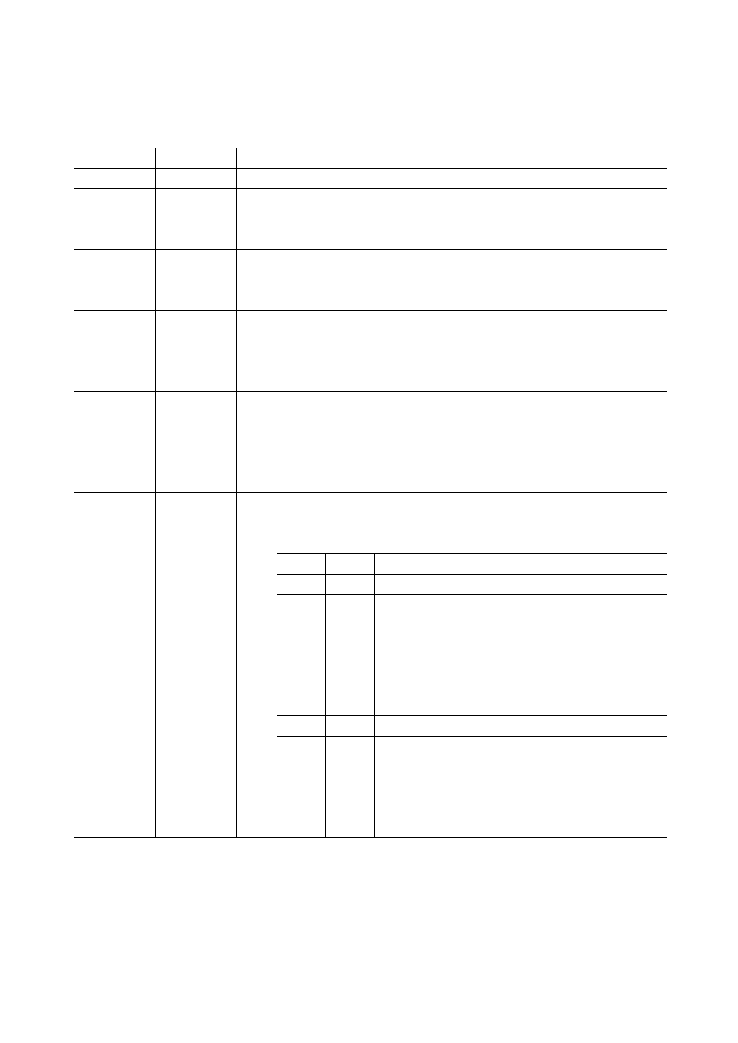
PIN DESCRIPTIONS (Continued)
Pin
Symbol Type
Description
43
TST
O Not used. Leave this pin open.
46
CLKIN
I Basic clock input pin.
Input a clock 18 to 20 MHz. Use 19.2 MHz if using internal synchronization
signals (SYNCO, SCKO).
47
VDD
I Power supply for PLL circuit that uses the basic clock.
(PLL)
Insert a 0.1mF capacitor with excellent high frequency characteristics
between VDD (PLL) and VSS (PLL).
48
VSS
I Ground for PLL circuit that uses the basic clock.
(PLL)
Insert a 0.1mF capacitor with excellent high frequency characteristics
between VDD (PLL) and VSS (PLL).
49
WDT2
O Not used. Leave this pin open.
50
DF2
O Tone disabler flag output pin for channel 2.
This pin outputs a disable flag when the ECDM pins are used for tone
disabler.
"H": Echo canceler disabled
"L": Echo canceler enabled
51
RGC20
I R input level control pins for channel 2 (refer to the block diagram).
52
RGC21
Excessive input (PCM level is at maximum value) causes a malfunction.
Use these pins when there is a possibility of excessive input.
RGC21 RGC20 Level Control Mode
0
0 Off
0
1 GC: On (control level = –20 dBm0)
By the R gain controller, levels from –20 to –11.5 dBm0
will be suppressed to –20 dBm0 and those above –11.5
dBm0 will always be attenuated by 8.5 dB. This is
effective to prevent excessive input and howling for
hands-free applications.
1
0 Inhibited
1
1 ±6LR: On
Apply –6 dB to excessive inputs using the level
adjuster provided on R and S I/O. Since +6 dB also
is applied at the output, the total level will not
change, making this effective against line echo.
11/28
Share Link: 