STK301-220 查看數據表(PDF) - SANYO -> Panasonic
零件编号
产品描述 (功能)
比赛名单
STK301-220 Datasheet PDF : 8 Pages
| |||
STK301-220
Pins f (1) through f (7) are used as pin connections for the
LC7522 band filter. Supported frequencies and their pin
assignments are listed in the following.
Pin Name Frequency
f (1)
60Hz
f (2)
150Hz
f (3)
400Hz
f (4)
1kHz
f (5)
2.5kHz
f (6)
6kHz
f (7)
15kHz
In order to minimize the noise which occurs during changeover,
connections are made using 1 MΩ resistors from pins f (1)
through f (7) to 1/2 VCC1.
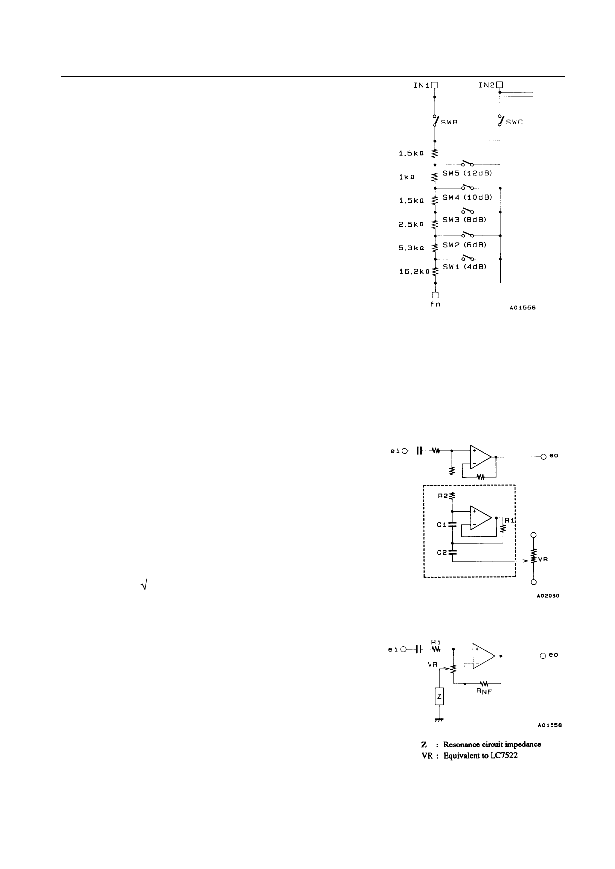
Resistor Equivalent Circuit
(single band)
Principles of Operation
The graphic equalizer section is constructed from 7 resonance circuits and output buffer amplifiers (every channel);
variable resistors (LC7522) and resonance circuit capacitors C1 and C2 are built-in. Resonance circuits utilize
semiconductor inductors and apply resonation to reduced impedance; all frequency gains are altered.
1. Resonance Circuit
Semiconductor inductors replace the L of the R, L, C series
resonance circuit with a CR element passing through the
buffer function of active elements such as the transistor and
op-amp (operational amplifier), thereby effecting the
equivalent operation of a R, L, C series resonance circuit.
The STK301-220 resonance circuit buffer is constructed
using transistors and arranged as illustrated in Figure 2.
Resonance frequency fo is determined using the following
formula:
fo =
1
2π C1 · C2 · R1 · R2
2. Flat, Boost and Cut
Gains matching resonance circuit frequency gains are altered
by altering the built-in resonance circuits and electronic
volume control. Figure 3 is presented to describe the
equivalent circuit. Z represents the impedance of the
resonance circuit in Figure 2.
Figure 2 Resonance Circuit
Figure 3 Equivalent Circuit
No. 4793-5/8
Share Link: 