PI74FCT245ATLE 查看數據表(PDF) - Pericom Semiconductor
零件编号
产品描述 (功能)
比赛名单
PI74FCT245ATLE Datasheet PDF : 7 Pages
| |||
PI74FCT245T
PI74FCT2245T(25 Ohm Series )
1122334455667788990011223344556677889900112233445566778899001122112233445566778899001122334455667788990011223344556677889900112211223344556677889900112233445566778899001122334455667788990011221122O334455c66t77a8899l00B1122i33d44i55r6677e88c99t00i11o2233n44a5566l77T8899r00a1122n1122s33c44e55i66v7788e99r0011s22
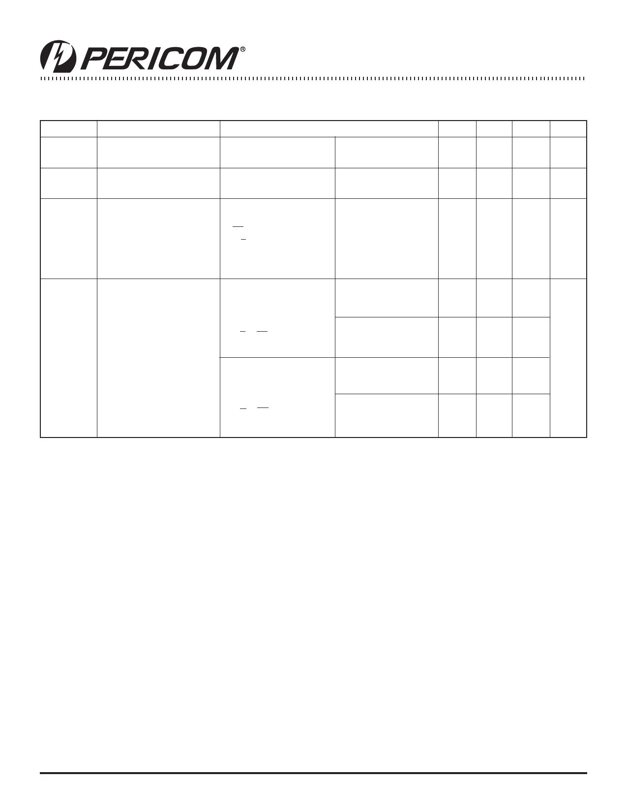
Power Supply Characteristics
Parameters Description
ICC
Quiescent Power
Supply Current
ΔICC
Supply Current per
Input @ TTL HIGH
ICCD
Supply Current per
Input per MHz(4)
IC
Total Power Supply
Current(6)
Test Conditions(1)
VCC = Max.
VIN = GND or VCC
VCC = Max.,
VIN = 3.4V(3)
VCC = Max.,
Outputs Open
OE = GND
T/R = GND or VCC
One Input Toggling
50% Duty Cycle
VCC = Max.,
Outputs Open
fI = 10 MHZ
50% Duty Cycle
T/R = OE = GND
One Bit Toggling
VCC = Max.,
Outputs Open
fI = 2.5 MHZ
50% Duty Cycle
T/R = OE = GND
Eight Bits Toggling
VIN = VCC
VIN = GND
VIN = VCC
VIN = GND
VIN = 3.4V
VIN = GND
VIN = VCC
VIN = GND
VIN = 3.4V
VIN = GND
Min. Typ(2) Max. Units
0.1 500 μA
0.5 2.0 mA
0.15 0.25 mA/
MHz
1.5 3.5(5) mA
1.8 4.5(5)
3.0 6.0(5)
5.0 14.0(5)
Notes:
1. For Max. or Min. conditions, use appropriate value specified under Electrical Characteristics for the applicable device.
2. Typical values are at VCC = 5.0V, +25°C ambient.
3. Per TTL driven input (VIN = 3.4V); all other inputs at VCC or GND.
4. This parameter is not directly testable, but is derived for use in Total Power Supply Calculations.
5. Values for these conditions are examples of the Icc formula. These limits are guaranteed but not tested.
6. IC =IQUIESCENT + IINPUTS + IDYNAMIC
IC = ICC + DICC DHNT + ICCD (fCP/2 + fINI)
ICC = Quiescent Current
ΔICC = Power Supply Current for a TTL High Input (VIN = 3.4V)
DH = Duty Cycle for TTL Inputs High
NT = Number of TTL Inputs at DH
ICCD = Dynamic Current Caused by an Input Transition Pair (HLH or LHL)
fCP = Clock Frequency for Register Devices (Zero for Non-Register Devices)
fI = Input Frequency
NI = Number of Inputs at fI
All currents are in milliamps and all frequencies are in megahertz.
06-0207
3
PS2012E 08/08/06
Share Link: 