LA2010 查看數據表(PDF) - SANYO -> Panasonic
零件编号
产品描述 (功能)
比赛名单
LA2010 Datasheet PDF : 8 Pages
| |||
LA2010
Recommended Operating Conditions at Ta = 25˚C
Parameter
Recommended supply voltage
Operating voltage range
Symbol
VCC
VCC op
Conditions
Operating Characteristics at Ta = 25˚C, VCC=9.0V, f=1kHz
Parameter
Symbol
Conditions
Circuit current
Output transistor saturation voltage
Output diode forward voltage
Input check kevel
Comparator (1) ON level
Comparator (1) OFF level
Comparator (2) ON level
Comparator (2) OFF level
Pin 4 reset level
Pin 8 reset voltage-1
Pin 8 reset voltage-2
ICC
VCE(Sat)
VF
VIN
VTH1-H
VTH1-L
VTH2-H
VTH2-L
V4R
V8R-1
V8R-2
f=1kHz, VIN=–30dB
I6=600mA
IF=600mA
f=1kHz, Pin 6 L → H
Pin 6 inverted
Pin 6 inverted
Pin 6 inverted
Pin 6 inverted
f=1kHz, VIN=–30dB, pin 8=1.0V
Pin 1 inverted, Rg=0
f=1kHz, VIN=–30dB, pin 4 inverted
Ratings
Unit
9V
3.5 to 14 V
Ratings
Unit
min typ max
11
22 mA
1.1
1.6 V
1.5
2.0 V
–47 –50 –53 dB
3.0
3.5
4.0 V
1.8
2.2
2.6 V
4.7
5.5
6.3 V
3.6
4.0
4.6 V
0.02
0.1 V
0.6
0.7
0.8 V
1.1
1.3
1.5 V
1. Description of external parts
· C1 : Input coupling capacitor
Capacitor used for coupling with preceding preamp. Characteristics at the time of application of power
considered, the capacitance value of C1 must not exceed that of C3 on pin 3. 0.047µF (polyester film
capacitor) is recommended. R1, R2 are used to adjust the input level. Pin 1 is high in input imedance ; in
order to be free from external effect, R2 must not exceed 10kΩ and must be grounded.
· C2, R3 : For setting interprogram space detect time (TD)
By selecting proper C2 and R3, your desired TD can be obtained.
TD=1.34×C2 · R3 (s)
It is recommended to use R3 of 150kΩ to 500kΩ.
It is recommended to use C2 of 0.22µF (polyester film capacitor).
· C3 :
NF capacitor
Lower cut-off frequency fL depends on this capacitor.
fL=
1
0.3πC3
(µF)
......... (kHz)
Assuming C3=0.47µF, fL=2.2kHz is obtained. If the capacitance
value of C3 is increased, fL lowers, thereby being subjected to
the effect of the variations in preamp. Further, since the time that
elapses between the moment VCC is applied and the moment the
circuit is stabilized becomes longer, the reset time must be made
longer accordingly. Therefore, it is recommended to use C3 of
0.47µF.
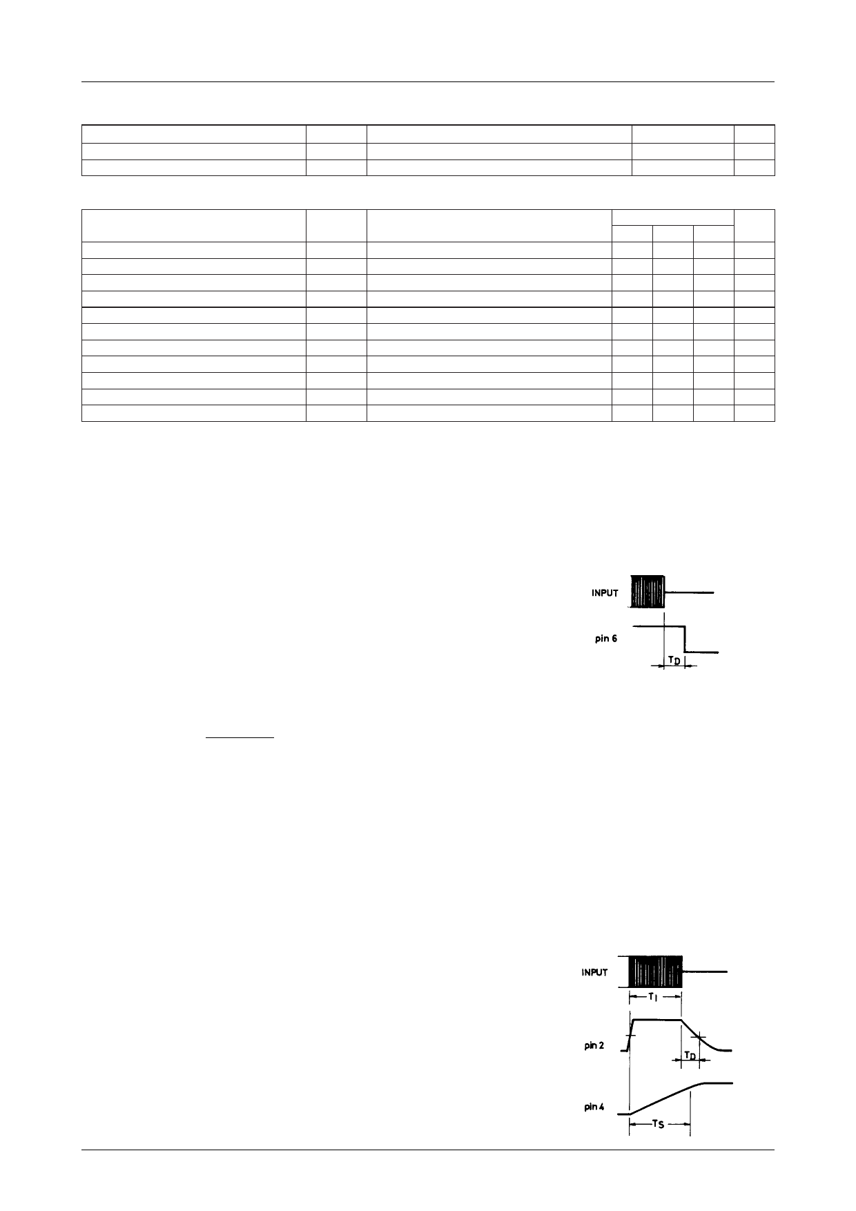
· C4, R4 : For setting recorded area detect time (TS)
The presence or absence of a program (input signal) is checked by the time setting determined by C4,
R4 as follows :
· For recorded area TS < TI + TD
· For unrecorded area TS > TI + TD
The recorded area detect time is set by :
TS=C4 (µF) R4 (kΩ) (ms)
Therefore, if the recorded area detect time (TS) is longer than the
input signal time (TI) + the unrecorded area detect time (TD), no
program is present. The resistance value of R4 must be 50kΩ to
200kΩ ; it is recommended to use R4 of 100kΩ. The capacitance
value of C4 must not exceed 4.7µF ; it is recommended to use C4
of 1µF to 3.3µF.
No.1343–2/8
Share Link: 