FX806A 查看數據表(PDF) - CML Microsystems Plc
零件编号
产品描述 (功能)
比赛名单
FX806A Datasheet PDF : 13 Pages
| |||
Controlling Protocol
Control of the functions and levels within the FX806A PLMR Audio Processor is by a group of Address/Commands and
appended data instructions from the system µController to set/adjust the functions and elements of the FX806A. The use of
these instructions is detailed in the following paragraphs and tables.
Command
Assignment
Address/Command (A/C) Byte
Hex
Binary
MSB
LSB
General Reset
01
Control Command
10
Mode Command
11
Mod. Levels Set
12
Volume Set
13
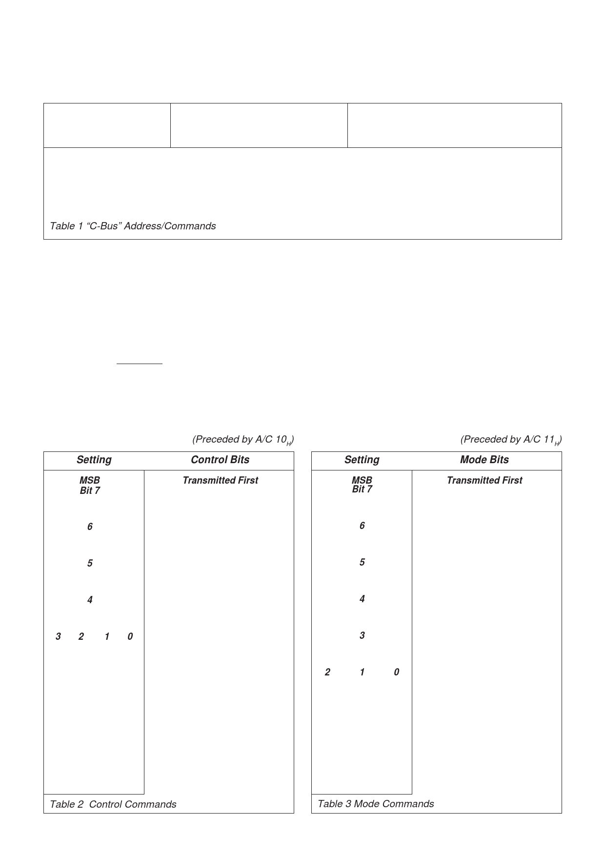
Table 1 “C-Bus” Address/Commands
00000001
00010000
00010001
00010010
00010011
Command
Data
Table
+
1 byte
2
+
1 byte
3
+
2 bytes
4
+
1 byte
5
In “C-BUS” protocol the FX806A is allocated Address/
Command (A/C) values 10H to 13H. “C-BUS” Command,
Mode, Modulation and Volume assignments and data
requirements are given in Table 1 and illustrated in Figure 5
(Main Block Diagram). Each instruction consists of an
Address/Command (A/C) byte followed by a data instruction
formulated from the following tables.
Commands and Data are only to be loaded in the group
configurations detailed, as the “C-BUS” interface recognises
the first byte after Chip Select (logic “0”) as an Address/
Command.
Function or Level control data, which is detailed in Tables 2,
3, 4 and 5, is acted upon at the end of the loaded instruction.
Upon Power-Up the value of the “bits” in this device will be
random (either “0” or “1”). A General Reset Command (01H)
will be required. This command is provided to “reset” all
devices on the “C-BUS” and has the following effect on the
FX806A.
Control Address Command
Mode Address Command
Volume Set
Loaded as 00
H
Loaded as 00
H
Loaded as 00
H
Control Command
Setting
(Preceded by A/C 10H)
Control Bits
Mode Command
Setting
(Preceded by A/C 11H)
Mode Bits
MSB
Bit 7
0
1
6
0
1
5
0
1
4
0
1
32
00
00
00
00
01
01
01
01
10
10
10
10
11
11
11
11
10
00
01
10
11
00
01
10
11
00
01
10
11
00
01
10
11
Transmitted First
Audio Output (Rx)
Disabled
Enabled
Modulation Drives
Disabled
Enabled
Pre-Emphasis
By-Pass
Enabled
Input Select
Rx Audio In
Mic. In
Input Level Set
Input Amp Disabled
-4.0dB
-3.0dB
-2.0dB
-1.0dB
0dB
1.0dB
2.0dB
3.0dB
4.0dB
5.0dB
6.0dB
7.0dB
8.0dB
9.0dB
10.0dB
MSB
Bit 7
0
1
6
0
1
5
0
1
4
0
1
3
0
1
2
1
0
0
0
0
0
0
1
0
1
0
0
1
1
1
0
0
1
0
1
1
1
0
1
1
1
Transmitted First
Drive Source
Signals
Calibration
Deviation Limiter
Disabled
Enabled
VOGAD
Disabled
Enabled
De-Emphasis
Enabled
By-Passed
Signal Select
Internal
External
Process Gain Set
-4.0dB
-3.0dB
-2.0dB
1.0dB
0dB
1.0dB
2.0dB
3.0dB
Table 2 Control Commands
Table 3 Mode Commands
7
Share Link: 