SS6639 查看數據表(PDF) - Silicon Standard Corp.
零件编号
产品描述 (功能)
比赛名单
SS6639 Datasheet PDF : 12 Pages
| |||
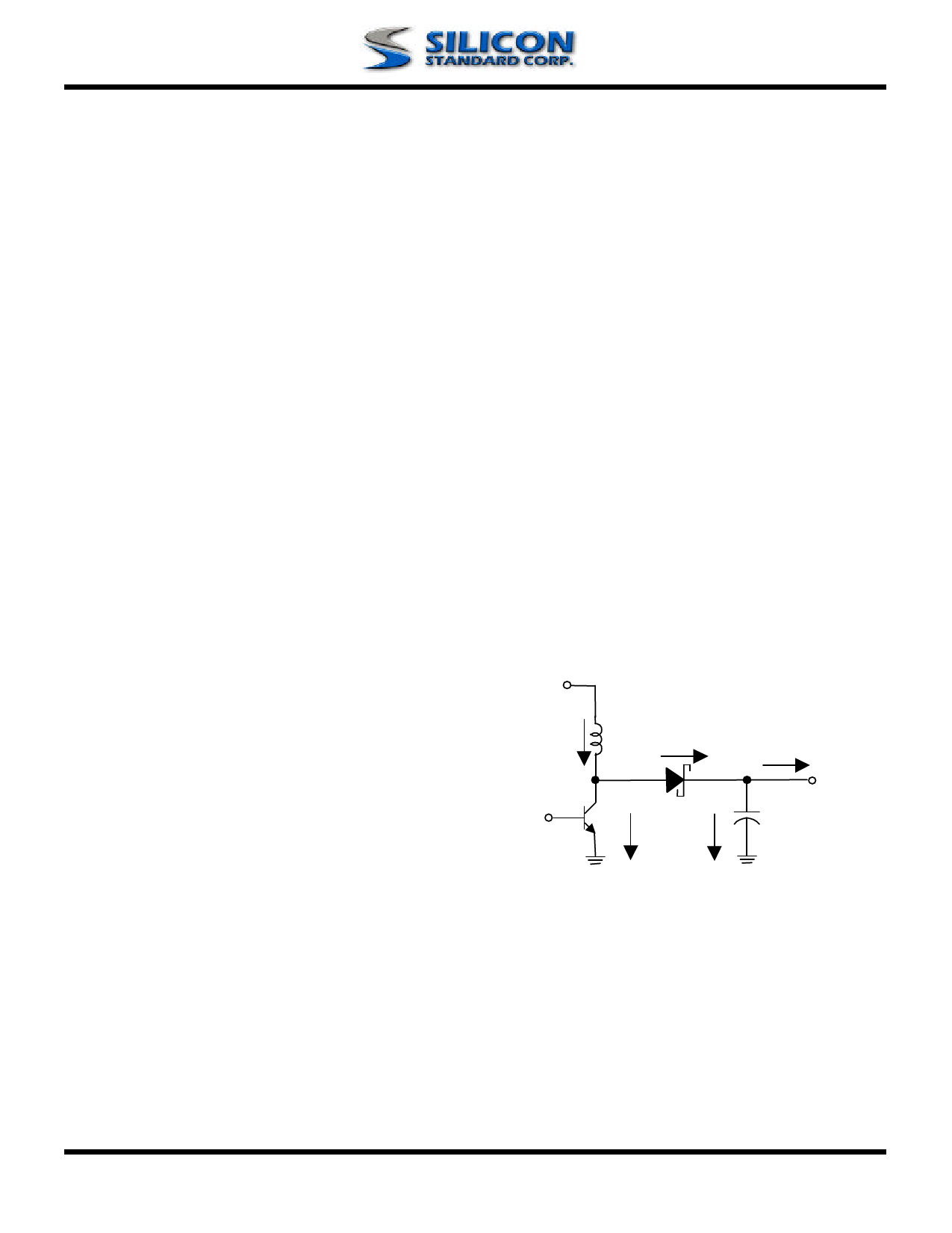
n PIN DESCRIPTIONS
Pin 1: GND:
Pin 2: VOUT:
Ground. Must be low impedance;
solder directly to ground plane.
IC supply pin. Connect Vout to the
regular output.
SS6639
Pin 3: EXT:
Push-pull driver output for external
power. Switch.
n APPLICATION INFORMATION
General Description
The SS6639 PFM (pulse frequency modulation)
controller IC combines a switch mode regulator, a
push-pull driver, a precision voltage reference, and a
voltage detector in a single monolithic device. It
offers extremely low quiescent current, high
efficiency, and very low gate-threshold voltage to
ensure start-up with low battery voltage (0.8V typ.).
Designed to maximize battery life in portable
products, it minimizes switching losses by only
switching as needed to service the load.
PFM controllers transfer a discrete amount of energy
per cycle and regulate the output voltage by
modulating the switching frequency with a constant
turn-on time. Switching frequency depends on load,
input voltage, and inductor value and can range up
to 100 KHz.
When the output voltage drops, the error comparator
enables the 100 kHz oscillator which turns the
MOSFET on for around 7.5us and off for 2.5µs.
Turning on the MOSFET allows inductor current to
ramp up, storing energy in the magnetic field.
When the MOSFET turns off, the inductor forces
current through the diode to the output capacitor and
the load. As the stored energy is depleted, the
current ramps down until the diode turns off. At this
point, the inductor may ring due to residual energy
and stray capacitance. The output capacitor stores
charge when current flowing through the diode is
high, and releases it when current is low, thereby
maintaining a steady voltage across the load.
As the load increases, the output capacitor
discharges faster and the error comparator initiates
cycles sooner, increasing the switching frequency.
The maximum duty cycle ensures adequate time for
energy transfer to the output during the second half
of each cycle. Depending on the circuit, PFM
controllers can operate in either discontinuous mode
or continuous conduction mode. The continuous
conduction mode means that the inductor current
does not ramp to zero during each cycle.
VIN
IIN
SW
EXT
Isw
ID
IOUT
+
VOUT
Ico
Discontinuous Conduction Mode
Rev.2.01 6/26/2003
www.SiliconStandard.com
8 of 12
Share Link: 