LD83C51FC-1 查看數據表(PDF) - Intel
零件编号
产品描述 (功能)
比赛名单
LD83C51FC-1 Datasheet PDF : 20 Pages
| |||
8XC51FX
Down is the last instruction executed. The on-chip
RAM and Special Function Registers retain their val-
ues until the Power Down mode is terminated.
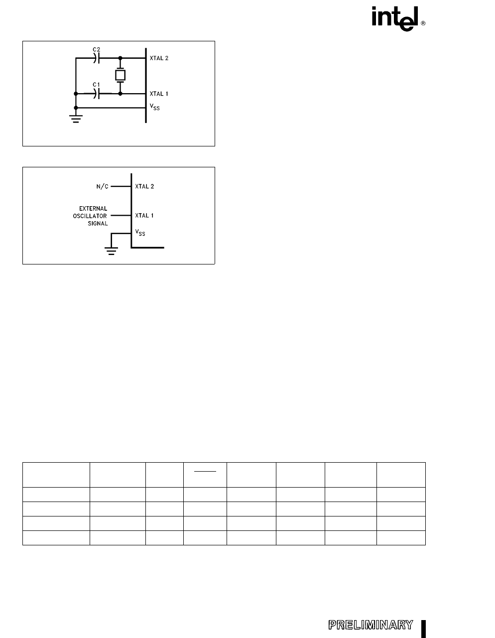
272322 ±3
C1, C2 e 30 pF g10 pF for Crystals
For Ceramic Resonators, contact resonator manufacturer.
Figure 3. Oscillator Connections
On the 8XC51FX either hardware reset or external
interrupt can cause an exit from Power Down. Reset
redefines all the SFRs but does not change the on-
chip RAM. An external interrupt allows both the
SFRs and the on-chip RAM to retain their values.
To properly terminate Power Down the reset or ex-
ternal interrupt should not be executed before VCC is
restored to its normal operating level and must be
held active long enough for the oscillator to restart
and stabilize (normally less than 10 ms).
272322 ±4
With an external interrupt, INT0 or INT1 must be en-
abled and configured as level-sensitive. Holding the
pin low restarts the oscillator but bringing the pin
back high completes the exit. Once the interrupt is
serviced, the next instruction to be executed after
RETI will be the one following the instruction that put
the device into Power Down.
Figure 4. External Clock Drive Configuration DESIGN CONSIDERATION
IDLE MODE
The user's software can invoke the Idle Mode. When
the microcontroller is in this mode, power consump-
tion is reduced. The Special Function Registers and
the onboard RAM retain their values during Idle, but
the processor stops executing instructions. Idle
Mode will be exited if the chip is reset or if an en-
abled interrupt occurs. The PCA timer/counter can
optionally be left running or paused during Idle
Mode.
POWER DOWN MODE
To save even more power, a Power Down mode can
be invoked by software. In this mode, the oscillator
is stopped and the instruction that invoked Power
Ambient light is known to affect the internal RAM
contents during operation. If the 87C51FX appli-
cation requires the part to be run under ambient
lighting, an opaque label should be placed over
the window to exclude light.
When the idle mode is terminated by a hardware
reset, the device normally resumes program exe-
cution, from where it left off, up to two machine
cycles before the internal reset algorithm takes
control. On-chip hardware inhibits access to inter-
nal RAM in this event, but access to the port pins
is not inhibited. To eliminate the possibility of an
unexpected write when Idle is terminated by re-
set, the instruction following the one that invokes
Idle should not be one that writes to a port pin or
to external memory.
Table 2. Status of the External Pins during Idle and Power Down
Mode
Program
Memory
ALE
PSEN
PORT0
PORT1
PORT2
PORT3
Idle
Internal
1
1
Data
Data
Data
Data
Idle
External
1
1
Float
Data
Address
Data
Power Down
Internal
0
Power Down
External
0
0
Data
Data
Data
Data
0
Float
Data
Data
Data
NOTE:
For more detailed information on the reduced power modes refer to current Embedded Microcontrollers and Processors
Handbook Volume I, and Application Note AP-252 (Embedded Applications Handbook), ``Designing with the 80C51BH.''
6
Share Link: 