VSK-S5-3R3UA 查看數據表(PDF) - CUI INC
零件编号
产品描述 (功能)
比赛名单
VSK-S5-3R3UA Datasheet PDF : 6 Pages
| |||
For more information, please visit the product page.
CUI Inc │ SERIES: VSK-S5│ DESCRIPTION: AC-DC POWER SUPPLY
date 01/08/2014 │ page 5 of 6
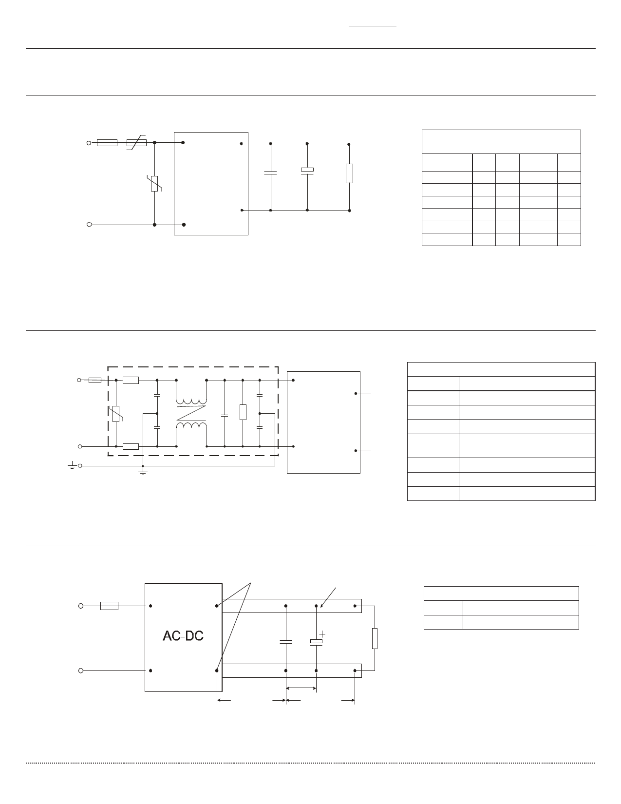
TYPICAL APPLICATION CIRCUIT
FUSE NTC
L
L +Vo
C1 C2
Figure 1
MOV
+
RL
-Vo
N
N
Table 1
Recommended External Circuit
Components
MODEL
C11
C21
(μF) (μF)
FUSE
NTC
VSK-S5-3R3UA 1
47 1 A/250 V 5D-9
VSK-S5-5UA
1
47 1 A/250 V 5D-9
VSK-S5-9UA
1
33 1 A/250 V 5D-9
VSK-S5-12UA
1
33 1 A/250 V 5D-9
VSK-S5-15UA
1
33 1 A/250 V 5D-9
VSK-S5-24UA
1
10 1 A/250 V 5D-9
Note:
1. Output filtering capacitor C1 is a ceramic capacitor that is used to filter high frequency noise. C2 is an electrolytic capacitor. It is recommended to use high frequency and
low impedance electrolytic capacitors. For capacitance and current of capacitor please refer to the manufacturer’s datasheet. Voltage derating of capacitor should be 80%
or above.
EMC RECOMMENDED CIRCUIT
FUSE
R2
L
CY1
Figure 2
N
MOV
R1
CY2
CY3
LCM CX
R3
CY4
L
ACDC
N
OUT PUT
Table 2
Recommended External Circuit Components
FUSE
1 A/250 V
MOV
561KD14
R1, R2
2Ω/3W winding resistor
R3
1MΩ/2W
CY1, CY2,
CY3, CY4
1000pF/400Vac
CX
0.22μF/275Vac
LCM
10mH-30mH
CY
Y capacitor, 102K/400V
TEST CONFIGURATION
FUSE
L
Figure 3
N
Connect Oscillograph Probe
Copper sheet
+Vo
C1
C2
Load
-Vo
12.7mm
25.4mm
25.4mm
Table 3
Capacitors
C1 1μF ceramic capacitor
C2 10μF electrolytic capacitor
Note:
1. All specifications measured at Ta=25°C, humidity <75%, 220 Vac input voltage, and rated output load, unless otherwise specified.
cui.com
Share Link: 