LC19001A010 查看數據表(PDF) - SANYO -> Panasonic
零件编号
产品描述 (功能)
比赛名单
LC19001A010 Datasheet PDF : 8 Pages
| |||
Continued from preceding page.
Reset
Parameter
Status diagnostic function
Interface diagnostic function
Menu area function
Reference value setup function
Duplicate coordinate processing
function
Timeout function
Noise exclusion function
Lock function
LC19001A010
Function
Description
Hardware reset
Software reset
Power on reset
There are four types of reset: hardware reset, software reset, power on reset, and
watchdog reset.
Operation starts after the oscillator stabilization period has elapsed when stop
mode is cleared and after a power on reset.
Watchdog reset
A reset function operates automatically if the application software fails.
Control setting state
verification
Sends the controller’s current state of the settings to the host CPU.
Information sent includes the coordinate calculation method, the data output
mode, and the output rate.
Interface verification
Uses arbitrary data to verify whether communication between the controller and
the host CPU is functioning normally.
Menu area registration
A menu area can be registered at an arbitrary location.
Up to 24 menu items can be registered.
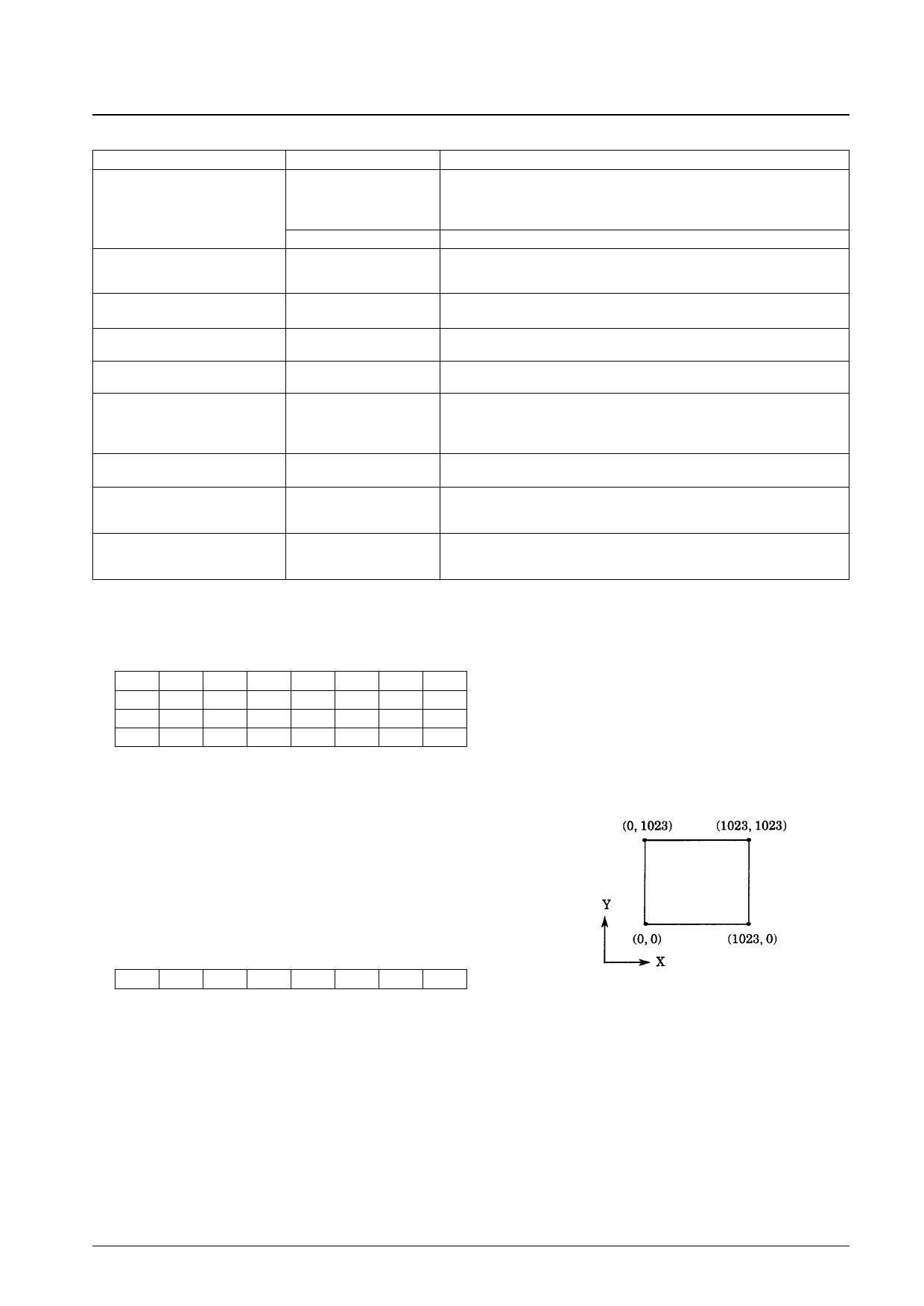
Matching positions
Accepts A/D values and reference coordinate values from the host CPU for use in
normalizing the A/D converted data and in matching positions.
Duplicate coordinates are not
transmitted
Compares the coordinate values transferred in the previous operation with the
current coordinate data and if the coordinate values are the same (i.e., if they are
duplicate coordinate values) the LC19001A010 does not send the current
coordinate data. (Only valid in stream mode)
Sets the timeout time
If the required data was not received within the preset timeout time, the controller
sends F3h to the host CPU.
Sets the parameters used to
reduce noise levels
Normally set to be about 10% of the number of pixels. (only valid in normalized
mode)
Initial values: X = 64, Y = 48
Starts and clears the lock
function
If a lock command is issued, after transmitting the coordinate data currently being
transmitted, the controller halts transmission.
The lock state is cleared by sending a lock clear command.
Coordinate Data Output Format: 4-byte structure
bit 7
6
5
4
3
2
1
0
Ph
0
0
P
X3
X2
X1
X0 First byte
0
0
X9
X8
X7
X6
X5
X4 Second byte
0
0
0
0
Y3
Y2
Y1
Y0 Third byte
0
0
Y9
Y8
Y7
Y6
Y5
Y4 Fourth byte
• Ph:
Phase bit, always set to 1.
• 0:
Zero bits, always cleared to 0.
• X0 to X9: Horizontal axis value (X) as a binary value (X9 is the high-order bit)
• Y0 to Y9: Vertical axis value (Y) as a binary value (Y9 is the high-order bit)
• P:
Pen status (pen down = 1, pen up = 0)
– When the pen is in the up state, the LC19001A010 sends a single byte with the value 80 h.
Menu Area Number Output Format: 1-byte structure
bit 7
6
Ph
1
5
4
3
2
1
0
0
M4
M3
M2
M1
M0 First byte
• Ph:
Phase bit, always set to 1.
• 1:
One bit, always set to 1.
• 0:
Zero bit, always cleared to 0.
• M0 to M4: Menu number M (range: 1 to 24) as a binary value (M4 is the high-order bit)
– When the pen is in the up state, the LC19001A010 sends a single byte with the value 80 h.
Note : Coordinate data and menu area data can be differentiated by inspecting bit 6. (See the data format descriptions above.)
No. 5560-7/8
Share Link: 