MC74F539 查看數據表(PDF) - Motorola => Freescale
零件编号
产品描述 (功能)
比赛名单
MC74F539 Datasheet PDF : 3 Pages
| |||
DUAL 1-OF-4 DECODER
WITH 3-STATE OUTPUTS
The MC54 / 74F539 contains two independent decoders. Each accepts two
Address (A0 – A1) input signals and decodes them to select one of four
mutually exclusive outputs. A polarity control input (P) determines whether the
outputs are active HIGH (P = L) or active LOW (P = H). An active LOW input
Enable (E) is available for data demultiplexing; data is routed to the selected
output in non-inverted form in the active LOW mode or in inverted form in the
active HIGH mode. A HIGH Signal on the active LOW Output Enable (OE)
input forces the 3-state outputs to the high impedance state.
• Demultiplexing Capability
• 3-State Outputs
• Two Completely Independent 1-of-4 Decoders
• Input Clamp Diodes Limit High Speed Termination Effects
• ESD Protection > 4000 Volts
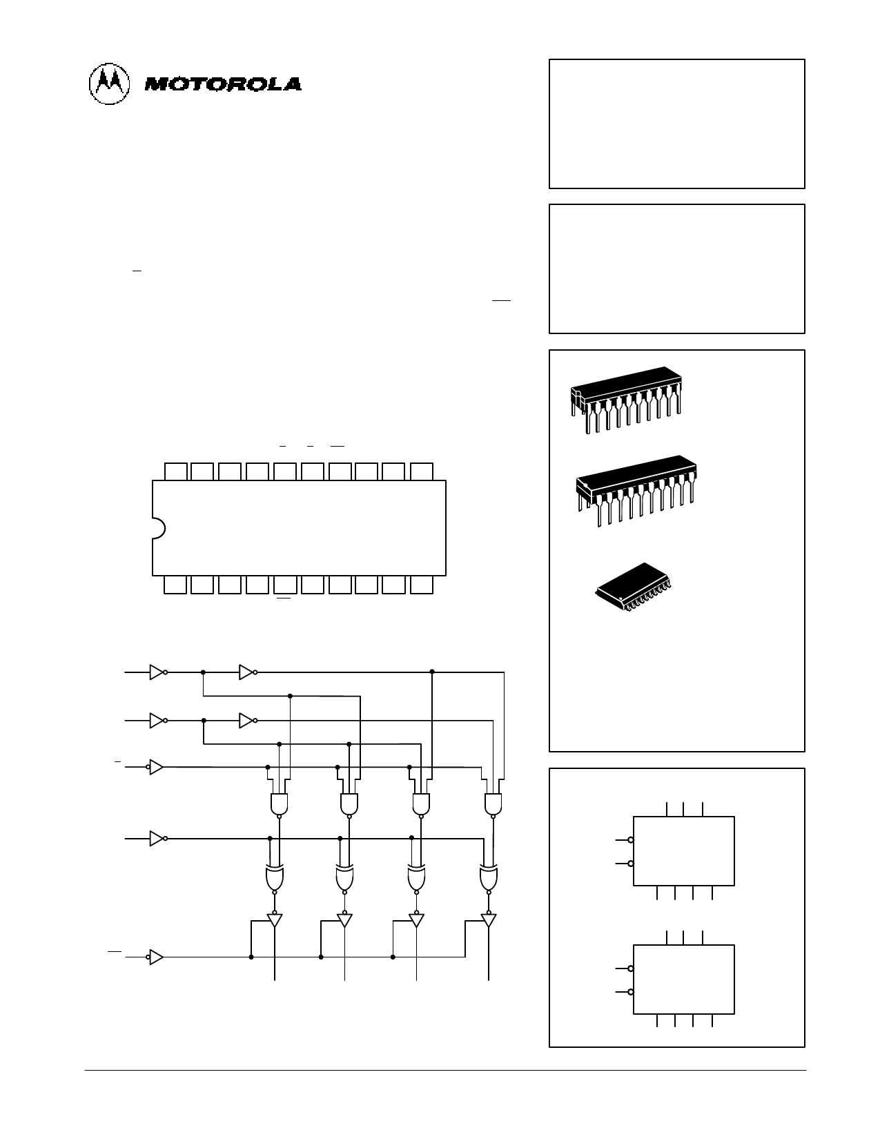
CONNECTION DIAGRAM DIP (TOP VIEW)
VCC O3b A1b A0b Eb Ea OEa Pa O0a O1a
20 19 18 17 16 15 14 13 12 11
1 2 3 4 5 6 7 8 9 10
O2b O1b O0b Pb OEb A0a A1a O3a O2a GND
LOGIC DIAGRAM (1/2 SHOWN)
A1
A0
E
P
OE
O0
O1
O2
O3
Please note that this diagram is provided only for the understanding of logic operations and
should not be used to estimate propagation delays.
MC54/74F539
DUAL 1-OF-4 DECODER
WITH 3-STATE OUTPUTS
FAST™ SCHOTTKY TTL
20
1
20
1
20
1
J SUFFIX
CERAMIC
CASE 732-03
N SUFFIX
PLASTIC
CASE 738-03
DW SUFFIX
SOIC
CASE 751D-03
ORDERING INFORMATION
MC54FXXXJ Ceramic
MC74FXXXN Plastic
MC74FXXXDW SOIC
LOGIC SYMBOL
13 6 7
P A0 A1
15 E
DECODER a
14 OE
O0 O1 O2 O3
12 11 9 8 VCC = PIN 20
4 17 18 GND = PIN 10
P A0 A1
16 E
DECODER b
5 OE
O0 O1 O2 O3
3 2 1 19
FAST AND LS TTL DATA
4-209
Share Link: 