TC74VHC4040F 查看數據表(PDF) - Toshiba
零件编号
产品描述 (功能)
比赛名单
TC74VHC4040F Datasheet PDF : 12 Pages
| |||
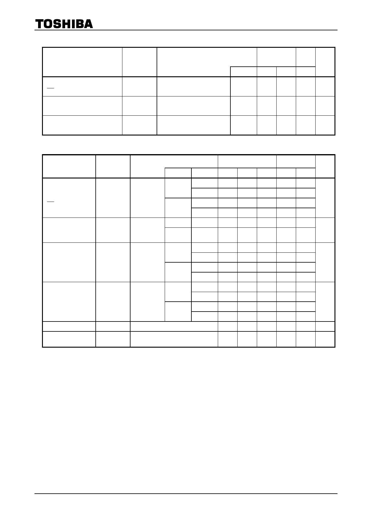
Timing Requirements (input: tr = tf = 3 ns)
Characteristics
Symbol
Minimum pulse width
( CK )
Minimum pulse width
(CLR)
Minimum removal time
tw (L)
tw (H)
tw (H)
trem
TC74VHC4040F/FN/FT/FK
Test Condition
―
―
―
Ta = 25°C
Ta =
−40 to
85°C Unit
VCC (V) Typ. Limit Limit
3.3 ± 0.3 ―
5.0 5.0
ns
5.0 ± 0.5 ―
5.0 5.0
3.3 ± 0.3 ―
5.0 5.0
ns
5.0 ± 0.5 ―
5.0 5.0
3.3 ± 0.3 ―
5.0 5.0
ns
5.0 ± 0.5 ―
5.0 5.0
AC Characteristics (input: tr = tf = 3 ns)
Characteristics
Symbol
Propagation delay
time
tpLH
( CK -Q1)
tpHL
Propagation delay
time
Δtpd
(Qn-Qn + 1)
Propagation delay
time
tpHL
(CLR-Q)
Maximum clock
frequency
Input capacitance
Power dissipation
capacitance
fmax
CIN
CPD
Test Condition
VCC (V) CL (pF)
15
3.3 ± 0.3
50
―
15
5.0 ± 0.5
50
3.3 ± 0.3
50
―
5.0 ± 0.5
50
Ta = 25°C
Min Typ. Max
―
7.5 11.9
― 10.0 15.4
―
4.8 7.3
―
6.3 9.3
―
2.4 4.4
―
1.6 3.1
15
―
8.3 12.8
3.3 ± 0.3
50
― 10.8 16.3
―
15
―
5.6 8.6
5.0 ± 0.5
50
―
7.1 10.6
15
75 140 ―
3.3 ± 0.3
50
55
80
―
―
15
150 210 ―
5.0 ± 0.5
50
95 125 ―
―
―
4
10
(Note) ―
21
―
Ta =
−40 to 85°C
Min Max
1.0 14.0
1.0 17.5
1.0 8.5
1.0 10.5
―
5.0
―
3.5
1.0 15.0
1.0 18.5
1.0 10.0
1.0 12.0
75
―
50
―
125 ―
80
―
―
10
―
―
Unit
ns
ns
ns
MHz
pF
pF
Note: CPD is defined as the value of the internal equivalent capacitance which is calculated from the operating
current consumption without load.
Average operating current can be obtained by the equation:
ICC (opr) = CPD·VCC·fIN + ICC
5
2007-10-01
Share Link: 