LPY4150ALTR 查看數據表(PDF) - STMicroelectronics
零件编号
产品描述 (功能)
比赛名单
LPY4150ALTR Datasheet PDF : 14 Pages
| |||
Application hints
5
Application hints
LPY4150AL
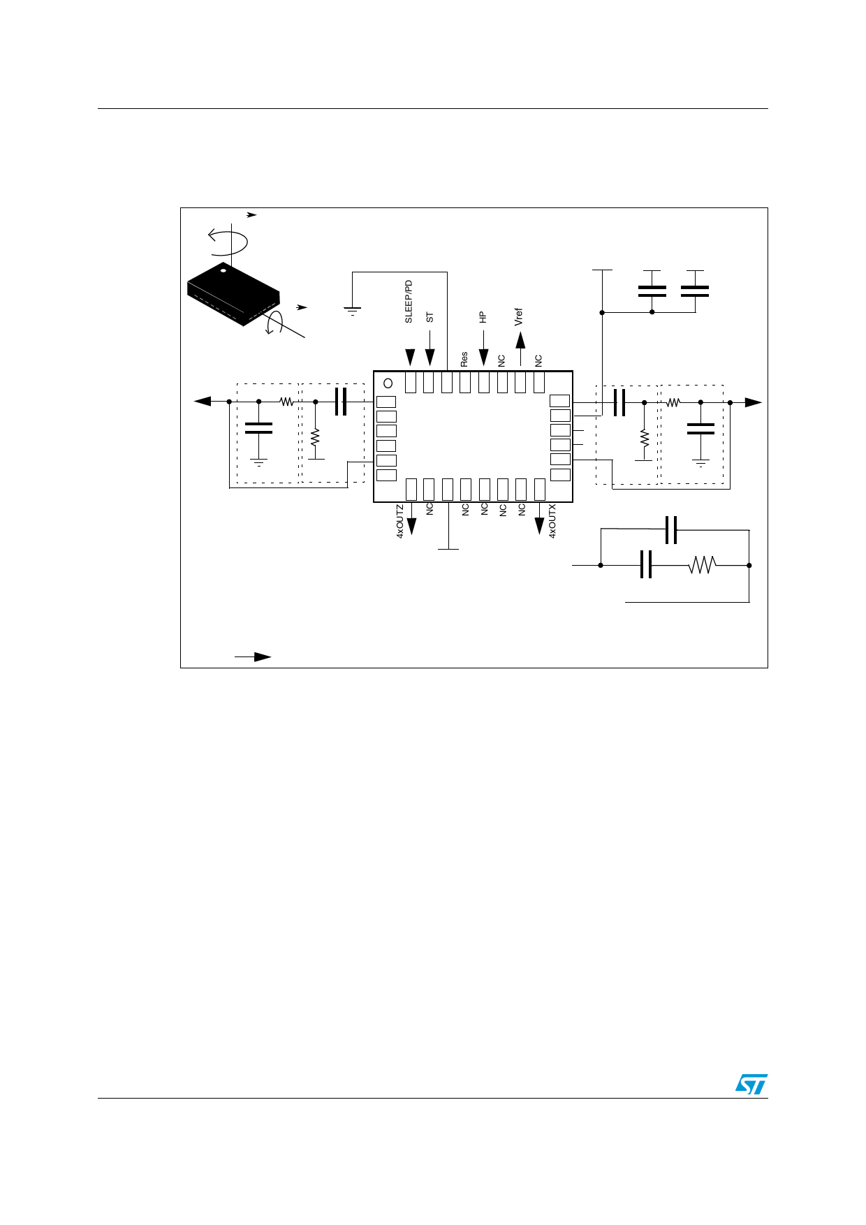
Figure 3. LPY4150AL electrical connections and external components values
::
4/0�6)%7
$)2%#4)/.�/&�4(%
$%4%#4!",%
!.'5,!2�2!4% 3
6DD
'.$ '.$
'.$
:X
�& �N&
.OT�AMPLIFIED�
FILTERED�OUTPUT�:
2
#
# .#
.#
2
.#
'.$
6REF
.#
2ECOMENDED /PTIONAL
,OWPASS�FILTER (IGHPASS�FILTER
4YPICAL�VALUES
2
�-/HM
#
�U&
2�
�K/HM
#�
�N&�TO�U&
2�
�K/HM
#
��N&
#
��N&
'.$
,09!&),,46$$
4OP�6IEW
&),4).�9
&),46$$
6#/.4
&),4/54�9�/54�9 .#
#
2
6REF
.OT�AMPLIFIED�
FILTERED�OUTPUT�8
2
#
'.$
#
6DD
#
&),4 6$$
2
6#/.4
$IGITAL�SIGNALS
!-6
Power supply decoupling capacitors (100 nF ceramic or polyester + 10 µF aluminum) should
be placed as near as possible to the device (common design practice).
The LPY4150AL allows band limiting of the output rate response through the use of an
external low-pass filter (recommended) in addition to the embedded low-pass filter (ft = 140
Hz).
The 4xOUTX and 4xOUTZ are, respectively, OUTX and OUTZ amplified output lines,
internally buffered to ensure low output impedance.
If external low-pass filtering is not applied, it is mandatory to short-circuit pin 1 to pin 5 and
pin 16 to pin 20, respectively, when amplified outputs are used.
When only a non-amplified output is used (OUTX/OUTZ), it is recommended to set pin 5
and 16 to a fixed reference voltage (Vref).
The LPY4150AL IC includes a PLL (phase-locked loop) circuit to synchronize driving and
sensing interfaces. Capacitors and resistors must be added at the FILTVDD and VCONT
pins (as shown in Figure 3) to implement a low-pass filter.
10/14
Doc ID 16581 Rev 1
Share Link: 