M74HC153TTR 查看數據表(PDF) - STMicroelectronics
零件编号
产品描述 (功能)
比赛名单
M74HC153TTR Datasheet PDF : 10 Pages
| |||
M74HC153
AC ELECTRICAL CHARACTERISTICS (CL = 50 pF, Input tr = tf = 6ns)
Test Condition
Value
Symbol
Parameter
VCC
(V)
tTLH tTHL Output Transition 2.0
Time
4.5
6.0
tPLH tPHL Propagation Delay 2.0
Time (Cn - Y)
4.5
6.0
tPLH tPHL Propagation Delay 2.0
Time (A, B - Y)
4.5
6.0
tPLH tPHL Propagation Delay 2.0
Time (G - Y)
4.5
6.0
TA = 25°C
-40 to 85°C -55 to 125°C Unit
Min. Typ. Max. Min. Max. Min. Max.
30 75
95
110
8 15
19
22 ns
7 13
16
19
48 115
145
175
15 23
29
35 ns
12 20
25
30
68 150
190
225
20 30
38
45 ns
16 26
32
38
30 85
105
130
10 17
21
26 ns
9 14
18
22
CAPACITIVE CHARACTERISTICS
Test Condition
Value
Symbol
Parameter
VCC
(V)
TA = 25°C
-40 to 85°C -55 to 125°C Unit
Min. Typ. Max. Min. Max. Min. Max.
CIN Input Capacitance 5.0
5 10
10
10 pF
CPD Power Dissipation
Capacitance (note 5.0
58
pF
1)
1) CPD is defined as the value of the IC’s internal equivalent capacitance which is calculated from the operating current consumption without
load. (Refer to Test Circuit). Average operating current can be obtained by the following equation. ICC(opr) = CPD x VCC x fIN + ICC/4(per circuit)
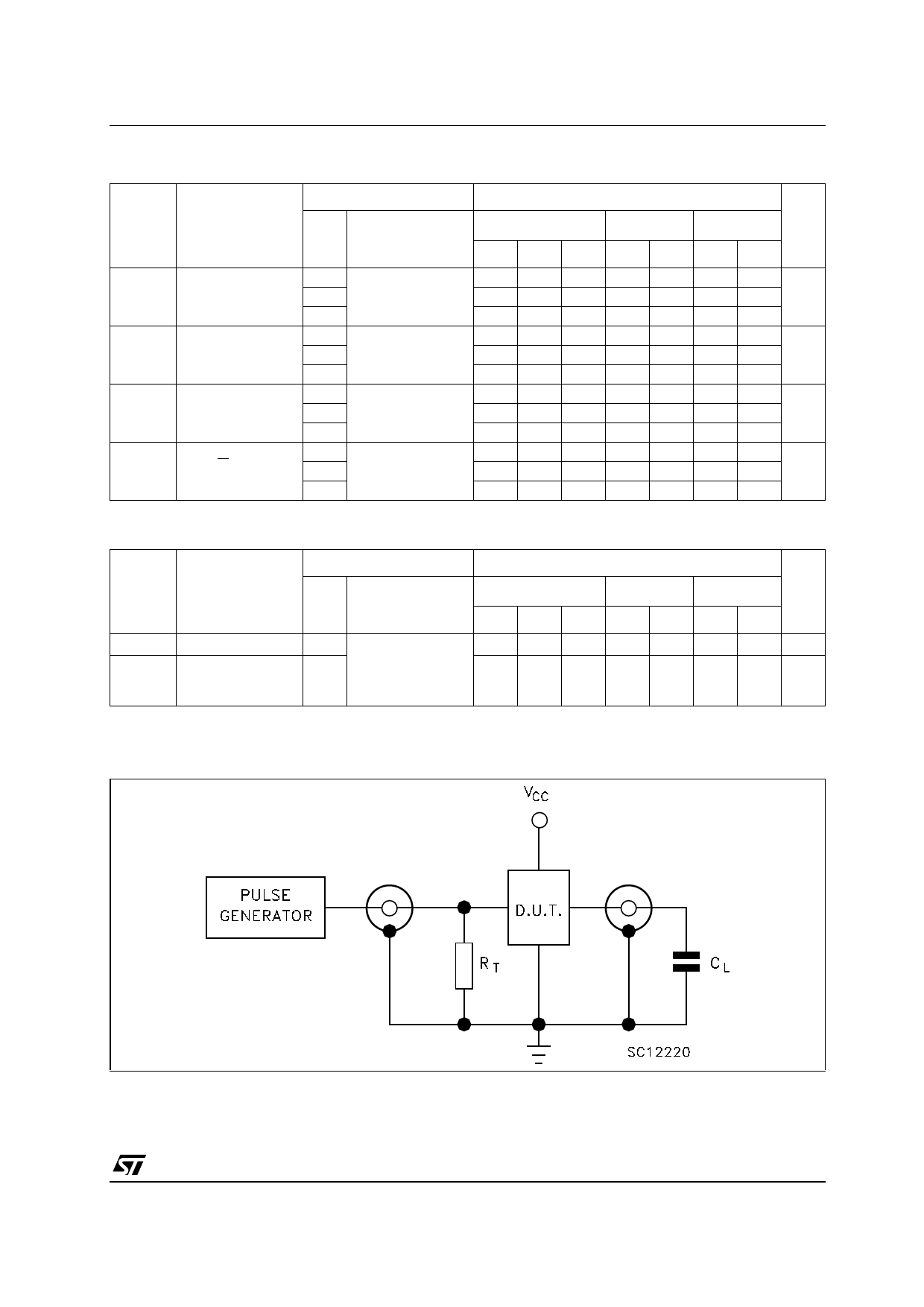
TEST CIRCUIT
CL = 50pF or equivalent (includes jig and probe capacitance)
RT = ZOUT of pulse generator (typically 50Ω)
5/10
Share Link: 