LT1680 查看數據表(PDF) - Linear Technology
零件编号
产品描述 (功能)
比赛名单
LT1680 Datasheet PDF : 16 Pages
| |||
LT1680
APPLICATIONS INFORMATION
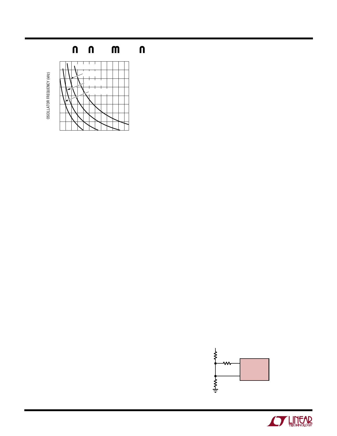
200
180
CCT = 0.68nF
CCT = 1nF
160
CCT = 1.5nF
140
CCT = 2.2nF
120
100
80
60
40
3 7 11 15 19 23 27 31 35 39 43 47
TIMING RESISTOR (kΩ)
1680 F02
Figure 2. Operating Frequency vs RCT, CCT
Average Current Limit
The average current limit function is implemented using
an external capacitor (CAVG) connected from IAVG to
SGND. This capacitor forms a single pole integrator with
the 50kΩ output impedance of the IAVG pin. The integrator
corner frequency is typically set 1 to 2 orders of magnitude
below the oscillator frequency and follows the relation:
f–3dB = (3.2)(10– 6)/CAVG
The average current limit function can be disabled by
shorting the IAVG pin directly to SGND. In some applica-
tions it is theoretically possible for the average current
limit circuit to overdrive the error amplifier output (VC pin)
beyond the operating range of the current sense compara-
tor. These applications include those where open-loop
system operation occurs, such as boost regulators in
output short-circuit condition, or in systems with poor
signal ground integrity. The potential for this overdrive can
be eliminated by connecting an external clamp diode
between the IAVG and VC pins (anode to IAVG and cathode
to VC). Connection of this diode will have no adverse
effects in any system and is recommended. This clamp is
required for all boost converter topologies.
Soft Start Programming
The LT1680 current control pin (VC) limits inductor cur-
rent to zero at voltages less than ≈0.7V through full
average current limit at VC ≈ 2.5V, yielding 1.8V over the
full regulation range of average load current. With the SS
pin at 0V, the VC pin is clamped to its zero inductor current
level. Given the typical soft start charge current of 10µA
and a soft start timing capacitor CSS, the start-up delay
time to full available average current will be:
tSS = (1.8)(105)(CSS)
Shutdown Function—Input Undervoltage Detect
and Threshold Hysteresis
The LT1680 RUN/SHDN pin uses a bandgap generated
reference threshold of about 1.25V. This precision thresh-
old allows use of the RUN/SHDN pin for both logic-level
shutdown applications and analog monitoring applica-
tions such as power supply sequencing.
Because an LT1680 controlled converter is a power trans-
fer device, a voltage that is lower than expected on the
input supply could require currents that exceed the sourc-
ing capabilities of that supply, causing the system to lock-
up in an undervoltage state. Input supply start-up protection
can be achieved by enabling the RUN/SHDN pin using a
resistor divider from the input supply to ground. Setting
the divider output to 1.25V when the supply is almost fully
enabled prevents the LT1680 regulator from drawing large
currents until the input supply is able to supply the
required power.
If additional hysteresis is desired for the enable function,
an external feedback resistor can be used from the LT1680
regulator output. If connection to the regulator output is
not desired, the 5VREF internal supply pin can be used.
Figure 3 shows an input supply sequencing configuration
on a 24V input converter. This configuration yields an
enable condition of 90% VIN (~ 21.5V) with about 10%
threshold hysteresis.
The shutdown function can be disabled by connecting the
RUN/SHDN pin to the 12VIN rail. This pin is internally
clamped to 2.5V through a 20k series input resistance and
will therefore draw 0.5mA when tied directly to 12V. This
VIN
24V
160k
16
5VREF
390k
LT1680
11
RUN/SHDN
10k
1680 F03
Figure 3. Input Supply Sequencing Programming
10
Share Link: 