MPC2605ZP66R 查看數據表(PDF) - Motorola => Freescale
零件编号
产品描述 (功能)
比赛名单
MPC2605ZP66R Datasheet PDF : 30 Pages
| |||
AC OPERATING CONDITIONS AND CHARACTERISTICS
(TJ = 20 to + 110°C, Unless Otherwise Noted)
Input Timing Measurement Reference Level . . . . . . . . . . . . . . . 1.5 V
Input Pulse Levels . . . . . . . . . . . . . . . . . . . . . . . . . . . . . . . . . 0 to 3.0 V
Input Rise/Fall Time . . . . . . . . . . . . . . . . . . . . . . . . . . . . . . . . . . . . 2 ns
Output Measurement Timing Level . . . . . . . . . . . . . . . . . . . . . . . 1.5 V
Output Load . . . . . . . . . . . . . . . . . . . . . . . . 50 Ω Termination to 1.5 V
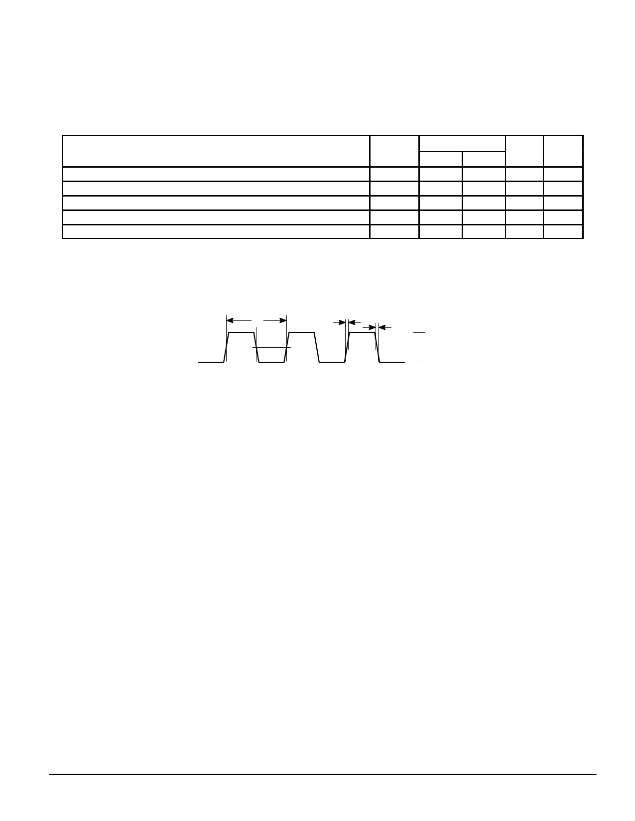
AC CLOCK SPECIFICATIONS
Parameter
Frequency of Operation
Clock Cycle Time
Clock Rise and Fall Time
Clock Duty Cycle Measured at 1.5 V
Clock Short–Term Jitter (Cycle to Cycle)
NOTES:
1. This parameter is sampled and not 100% tested.
2. Rise and fall times for the clock input are measured from 0.4 to 2.4 V.
Timing
Reference
,
MPC2605–66
Min
Max
—
66.67
15
—
1.0
2.0
40
60
—
± 150
Unit
MHz
ns
ns
%
ps
Notes
1, 2
1
CLOCK INPUT TIMING DIAGRAM
VM
VIH
VIL
VM = Midpoint Voltage (1.5 V)
MOTOROLA
MPC2605
7
Share Link: 