MAX1678EUA 查看數據表(PDF) - Maxim Integrated
零件编号
产品描述 (功能)
比赛名单
MAX1678EUA Datasheet PDF : 12 Pages
| |||
1-Cell to 2-Cell, Low-Noise,
High-Efficiency, Step-Up DC-DC Converter
Applications Information
Output Voltage Selection
The MAX1678 operates with a fixed 3.3V or adjustable
output. To select fixed-voltage operation, connect FB to
GND (Figure 7). For an adjustable output between 2V
and 5.5V, connect FB to a resistor voltage-divider
between OUT and GND (Figure 8). FB regulates to
1.23V.
Since FB leakage is 10nA max, select feedback resistor
R2 in the 100kΩ to 1MΩ range. R1 is given by:
R1
=
R2
x
VOUT
VREF
−
1
where VREF = 1.23V.
Maximum Output Current
and Inductor Selection
The MAX1678 is designed to work well with a 47µH
inductor in most low-power applications. 47µH is a suf-
ficiently low value to allow the use of a small surface-
mount coil, but large enough to maintain low ripple. The
Typical Operating Characteristics section shows perfor-
mance curves with several 47µH and 22µH coils. Low
inductance values supply higher output current but
also increase ripple and reduce efficiency. Note that
values below 22µH are not recommended due to
MAX1678 switch limitations. Higher inductor values
reduce peak inductor current (and consequent ripple
and noise) and improve efficiency, but also limit output
current.
The relationship between current and inductor value is
approximately:
IOUT(MAX)
=
Mx
1
2
x
K
L
x
VBATT
VOUT
where M is an empirical factor that takes into account
losses in the MAX1678 internal switches and in the
inductor resistance. K is the V-µs factor that governs
the inductor charge time. Nominally, M = 0.9 and
K = 8V-µs. M should be further reduced by 0.1 for each
ohm of inductor resistance.
The inductor’s saturation-current rating must exceed
the worst-case peak current limit set by the MAX1678’s
timing algorithm:
IPEAK
=
KMAX
L
where KMAX = 11.2V-µs. It is usually acceptable to
exceed most coil saturation-current ratings by 20% with
no ill effects; however, the maximum recommended IPEAK
for the MAX1678 internal switches is 550mA, so inductor
values below 22µH are not recommended. For optimum
efficiency, inductor series resistance should be less than
150mV/IPEAK. Table 1 lists suggested inductors and sup-
pliers.
Table 1. Suggested Inductors and Suppliers
PIN
INDUCTOR
PHONE
Coilcraft
DS1608C-223,
DS1608C-473
(847) 639-6400
Murata
LQH4N470K,
LQH3C470K
(814) 237-1431
Sumida
CD43-220,
CD43-470
(847) 956-0666
TDK
NLC453232T-220K,
NLC453232T-470K
(847) 390-4373
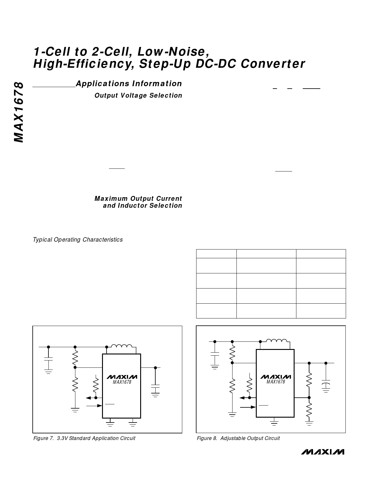
INPUT
0.87V TO VOUT
C1
R3
10µF
R4
L1
47µH, 200mA
BATT
LX
PFI
OUT
OUT
MAX1678
R5
PFO
SHDN
GND
FB
3.3VOUT
C2
10µF
INPUT
0.87V TO VOUT
C1
10µF
R3
R4
L1
47µH
BATT
LX
PFI
OUT
OUT
MAX1678
R5
PFO
FB
SHDN
GND
VOUT = 2V
TO 5.5V
R1
C2
R2
Figure 7. 3.3V Standard Application Circuit
Figure 8. Adjustable Output Circuit
10 ______________________________________________________________________________________
Share Link: 