FXAS21002CQR1 查看數據表(PDF) - Freescale Semiconductor
零件编号
产品描述 (功能)
比赛名单
FXAS21002CQR1 Datasheet PDF : 58 Pages
| |||
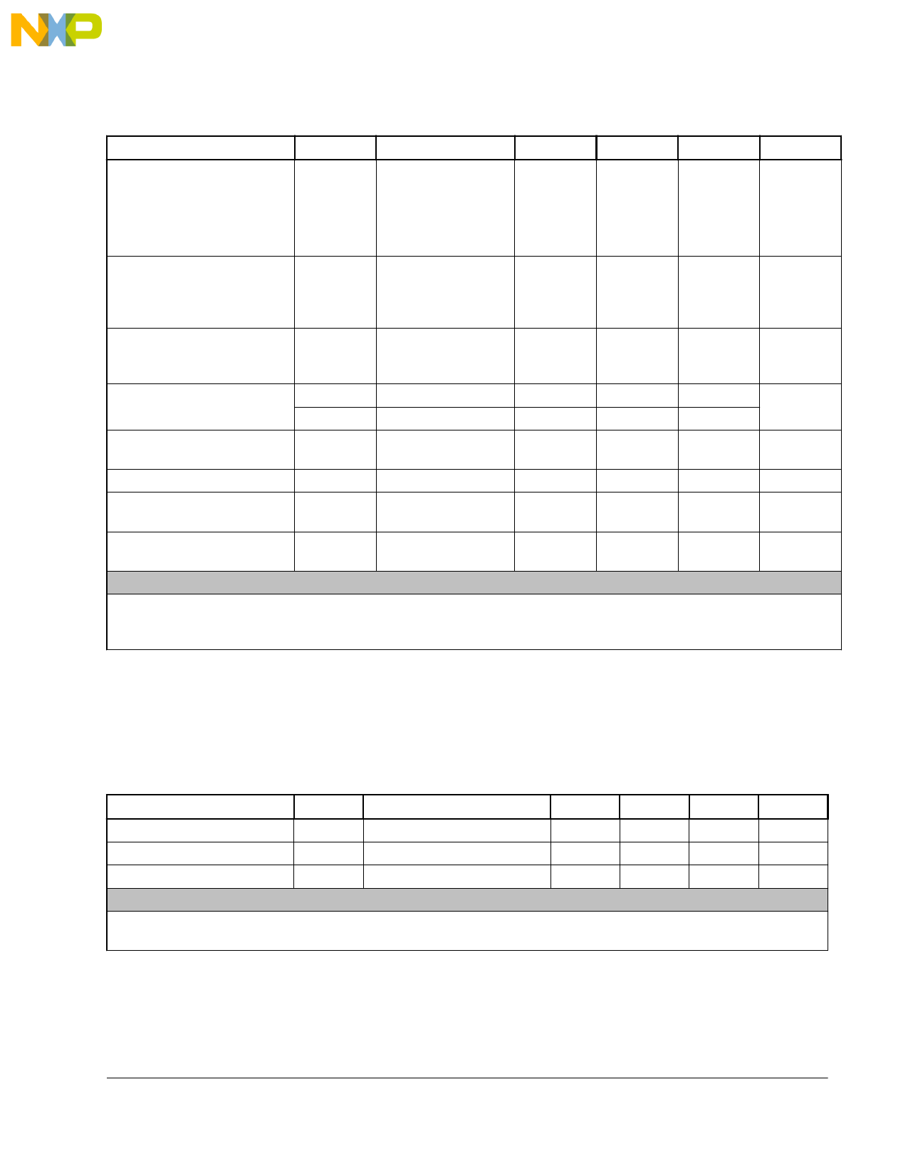
Mechanical and Electrical Specifications
Table 6. Electrical characteristics (continued)
Parameter
Symbol
Digital low level input voltage
SCL/SCLK, SDA/MOSI/
SPI_DATA, SA0/MISO, SPI/
VIL
I2C_B, RST_B, INT2/
PWR_CTRL, SPI_CS_B
High-level output voltage
INT1, INT2/PWR_CTRL,
SDA/MOSI/SPI_DATA, SA0/
MISO
VOH
Low-level output voltage INT1,
INT2/PWR_CTRL, SDA/
MOSI/SPI_DATA, SA0/MISO
VOL
Low-level output voltage SDA
Output Data Rate frequency
tolerance
VOLSDA1
VOLSDA2
ODRTOL
Output Signal bandwidth
BW
Standby to Active mode
transition time
TStdy-Act
Ready to Active mode
transition time
TRdy-Act
Test conditions (unless otherwise noted):
• VDD = 2.5 V
• VDDIO = 1.8 V
• T = 25°C
Test conditions
Min
—
—
Typ
Max
—
0.3 * VDDIO
IO = 1 mA
0.9 * VDDIO
—
—
IO = 1 mA
—
—
0.1 * VDDIO
IO = 3 mA, VDDIO ≥ 2V
—
IO = 3 mA, VDDIO < 2V
—
—
—
—
—
±2.5
0.4 * VDDIO
0.2 * VDDIO
—
—
4
< ODR/2
256
—
—
1/ODR + 60
—
—
—
1/ODR + 5
—
Unit
V
V
V
V
% ODR
Hz
ms
ms
2.5 Temperature Sensor Characteristics
Table 7. Temperature sensor characteristics
Characteristic
Symbol
Full-scale range
TFSR
Operating temperature
TOP
Sensitivity
TSENS
Test conditions (unless otherwise noted):
• VDD = 2.5 V
• VDDIO = 1.8 V
Condition(s)
—
—
—
Min
Typ
–40
—
–40
+25
—
1
Max
Unit
+85
°C
+85
°C
—
°C/LSB
3-Axis Digital Angular Rate Gyroscope, Rev. 2.1, 5/2015
11
Freescale Semiconductor, Inc.
Share Link: 